The LM3909 was considered a very exciting thing in spite of the fact that flashing a LED was pretty much all the LM3909 did. It did not produce particularly bright flashes. It did not even flash the LED all that quickly. It would however flash a LED for a very long time (years) from a single 1.5V cell. That was enough.
This was something new in the world. The LM3909 showed how profoundly different a light source the LED was compared to everything that had come before. People that did electronics for fun absolutely loved the LM3909 for providing this insight. At one time you could buy a LM3909 in pretty much any large shopping mall in North America (the ones containing a store called Radio Shack). Combining a LM3909, a capacitor and a battery just to watch a LED flash is something that pretty much everyone of my generation with an interest in electronics has done at one time or another.
The LM3909 did something sort of clever. A voltage of 1.5V was not enough to cause one of the red LEDs of the day to emit light. The LM3909 would charge up a several hundred uF capacitor to a significant fraction of the 1.5V battery voltage. It would then force the capacitor to be in series with the 1.5V power source causing the LED to light until the capacitor discharged. The capacitor was charged through a couple of resistors that drew relatively large currents when the capacitor was forced into series mode. To get reasonable efficiency the resistor values had to be on the larger side which limited the flash rate to something like once a second.
In the late 90's, I was enduring an entire team of people who were attempting to teach me undergraduate engineering math. This caused me to yearn for the life I had left behind (electronics). Due to the nature of the Electrical Engineering program I got to take my bicycle home in the dark fairly often. Once a woman in a van pulled over and told me a story with a very unhappy ending. It was about her friend who shared with me a love of stealthy bicycle travel. My thoughts naturally turned to lighting. Lighting involving electronics pretty much leaves some sort of LED flasher.
At various points during the ensuing project people would make the helpful suggestion that I could in fact just buy a bike flasher. I suppose those same people would suggest that a Jedi Master could hop into the land speeder and go pick up a light sabre. I didn't want just a bike flasher. I wanted the bike flasher. ... and well, the LM3909 was not it. It was power efficient at the cost of a very weak flash. I was sort of disappointed.
I still wanted to be able to use a single 1.5V cell so I used the idea of using a capacitor as a voltage multiplier as seen with the LM3909. I found that a 1000uf capacitor made for a reasonable flash. I wanted to use 3 LEDs with good lenses (10mm) adjusted to produce a fan of light directed down the road and somewhat to the sides. I just did not have enough light available that I could waste it. I eventually ended up with a single large power transistor switching individual 1000 uF capacitors for each LED. That was 3 amber LEDs and 3 capacitors on the front of the bike and 3 red LEDs and 3 capacitors on the back. I had to look to find some sort of convenient oscillator that would run on 1.5V (really 1V). Turned out that the LM3909 was ideal for the job and was used as the timing source. Sometimes you just can't avoid using the LM3909.
The flasher system was quite bright and was visible even on cloudy days. It served me well up to the point that the bicycle it was attached to was stolen from outside a post-university workplace. There was no on-off switch, I simply put a C cell in a battery holder on the bike frame. The battery life was pretty much perpetual. I didn't really care if I forgot and left the battery installed. I could have used a smaller/lighter power source but I do not like having to think about changing batteries.
We now draw a bit nearer to the actual point of this post... While investigating the present state of high power LEDs for a circadian light fixture project I spent some time wondering what a flasher using a high power LED would be like. I had felt limited by the amount of current I could blast the LEDs of the late 90's with. I was pulsing the LEDs with something like 100 mA. A 1W LED is rated for 350mA and can be pulsed to .5A-1A. They are also more efficient at converting electrical power to light. In particular I wanted a flasher bright enough to be seen in a urban streetlight environment from all directions.
I wanted to be able to retain the single C cell power source even if I ended up with a lot less battery life. Now, it turns out that .04 seconds is a kind of sweet spot for flash duration when dealing with human vision. For a given available optical energy, putting that energy into a .04 second flash produces the greatest perceived brightness. Doing the capacitor trick as before got me a capacitor value of around 0.22 Farad for a reasonable .04 second flash. That is a big capacitor. Fortunately there has been a recent technology breakthrough in the form of what are often called supercapacitors. I really needed .022 Farad with a low internal resistance (ESR). Contemporary supercaps do not roll that way. I could get a much larger value than I needed with a low ESR but that would make for a really large pulse. In the end I was still able to use the supercap to multiply the voltage of the battery but I had to do it a different way than the venerable LM3909 did.
The LEDs I was pulsing way back when had a forward voltage drop of around 2V. Typical high power LEDs are 2.5V for red and amber and 3.5V for green and blue/white. OK, goodbye to green and blue/white then. There is still a problem with red and amber. If we are only doubling the voltage the battery can only discharge to 1.25V (2*1.25V=2.5V). Dry cells are considered used up at about 1V. We are losing half the battery life. OK then, hello second supercap. Now we can triple the voltage. That does cause a pretty severe hit in terms of efficiency. Since there are no inductors here all extra voltage gets lost someplace in a resistance. The doubler has a maximum possible efficiency of 2.5V/(2*1.5V)=0.83 and the tripler comes out at 2.5V/(3*1.5)=0.56. Still, 56% efficiency with twice the battery life available is significantly better than 83%. We also need enough extra room to charge the capacitors with resistors. So the tripler is the way to go here. I will leave it as an exercise to come up with something better using an inductor.
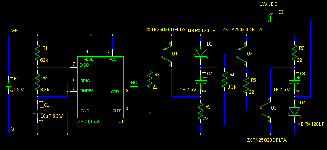
I still needed a timing source. The LM3909 is now discontinued (sniff) but you can get 555 timers designed to run off of a single 1.5V cell. I used the one from Zetex. Here is the schematic:
Here is a list of important parts used for the prototype (these were the ones in stock at Digi-Key at the time of the order):
1       ZXTN25020DFLTA          NPN low sat transistor sot-23
2       ZXTP25020DFLTA          PNP low sat transistor sot-23
1       ZSCT1555N8TA            lo volt 555 timer so-8
2       MBRX120LF               1A Schottky Diode sod-123
2       B0810-2R5105-R          1F supercap
1       LTPL-P011A              1W amber led
1       BHCL                    plastic C cell holder
1       9081CA                  so-8 proto board
U1 is just a 555 timer so I will not bother explaining how it works here. The values of R1, R2 and C1 gave a pulse length of 0.06 seconds and a period of 1.1 seconds with the prototype. Close enough I guess. By the way, the Zetex data sheet for the part seemed actively misleading. I had to figure out the timing (which is different from a normal 555 timer) on my own. The circuit formed by D1,C2 and R5 is the same thing as the circuit formed by R7, C3 and D2 (just turned over) so I will mostly just discuss one of them. C3 is charged during the non-pulse time through Schottky diode D2 and R7. The Schottky diode is quite over specified here in terms of maximum current. I was looking for a diode with low forward voltage at only 30mA. This one managed about 0.2V. Note that capacitor C3 never gets charged up to 1.5V. It only charges as much as is needed to fire the LED. That is because the RC time constant of C3 and R7 is relatively long at 22ohm*1F=22 seconds. This time constant means that the flasher actually needs to warm up over the course of 10 seconds or so before it reaches full brightness.
The LED fires when pin 3 of U1 goes low. Q3 is turned on through Q2 and drags the positive end of C3 to the V- rail. D2 is reverse biased and turns off. Let us assume that the V- rail is 0V. Then the negative end of C3 (and the negative end of the LED) is now as little as -1.5V. Q1 does the same sort of thing to C2 with respect to the V+ rail at +1.5V to drive the positive end of the LED as high as +3V. Thus potentially the LED could have as much as 4.5V across it. This would be too much voltage for the LED. The RC time constant mentioned previously prevents this excessive voltage at the LED. There simply isn't enough time for R7 to change the voltage of the capacitor any significant amount before the next pulse. Eventually an equilibrium is reached with the amount of charge going into the capacitor during charging time coming out during the LED pulse time. In practise the voltage across the capacitors is exactly enough to add together with the battery voltage to make up the LED voltage. It tends to be higher than expected because of the internal resistance of the capacitors when the led fires. The capacitors are rated at .4 ohms internal resistance and showed a drop of 0.2V with a 0.5A pulse. Lower internal resistance is better but makes for a more expensive supercapacitor.
And speaking of things that drop voltage, the transistors used here are special in that they drop very little voltage when turned on. They need to be driven hard to do this. For the old flasher I ended up using a transistor in a huge TO-220 package. As these transistors come in SOT-23 packages this ends up being a sort of technology improvement as well.
The LED current here is limited quite accurately by the combination of the value of R7 and the duty cycle of the pulse. This is possible due to the large value of the supercapacitor and is a very nice result. Unfortunately as the battery voltage drops the voltage across R7 drops. That means that the LED gets dimmer over time. With the prototype the combination of extra voltage available due to tripling combined with the internal resistance of the capacitors produced a situation where the LED brightness was still a bit more than a third of the full voltage brightness when the battery hit 1V ("dead"). That is also a nice result. This could be improved by finding a less voltage sensitive way to charge the capacitors.
Here is what the prototype looked like:
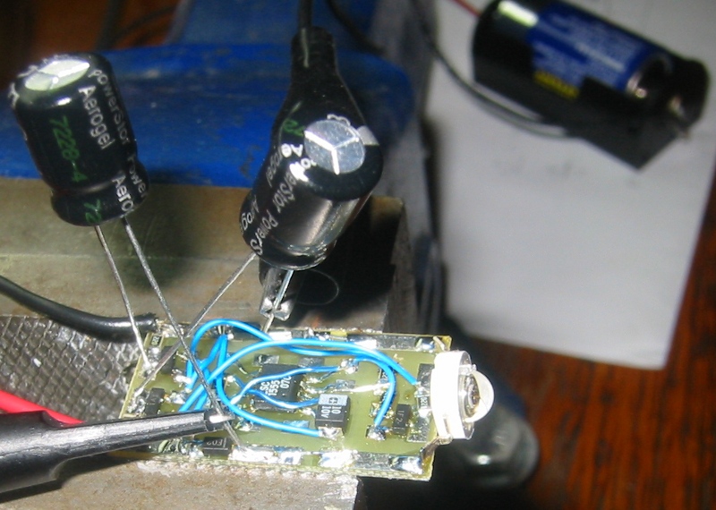
With a new battery it produced pulses of about 0.5A. The light output is really intense ... which is good. I think that battery life should be something like 100 hours with a C cell and 150 hours with a D cell. The front and back dual flasher I now hope to build should thus get about 50 hours on a C cell.
This flasher suffers from a problem I refer to as the infinite battery life syndrome. You often see bicycle flashers in the wild producing barely perceptible light output. I think that is caused by a combination of human perception and the characteristics of LEDs. As the battery voltage gets closer and closer to the LED forward voltage the current decreases and as a result the battery life increases. Eventually the current gets down into the microamp range but the LEDs are still showing light. Since people are really bad at judging brightness there never comes a time where it is obvious that the battery needs to be changed. Since this is safely critical equipment I do not think this is good design. Presently the prototype is happily producing 63 mA (0.07V across R5 while charging) pulses at a battery voltage of 0.83V after running steady for a week and a half and now seems fairly stable. I guess one could add a voltage detector and do something on low battery voltage. I have no idea what this something should be.
I know that 1 second period flashers are considered with some disdain in some quarters. The issue is that it makes it difficult for observers to infer the speed and direction of the bicycle. I can rebut this from experience as I have used such a flasher for some years. On a totally dark street there might be an issue but in an urban environment if you can draw attention to yourself there is almost always enough light to follow the path of the bicycle/rider afterwards. This is especially true if the bicycle is liberally plastered with reflective tape as mine is. Since attracting attention is important it seems reasonable to throw out as much light energy as possible during the pulse. The best way to do this is to pulse as infrequently as is practical.
The stuff about the pulse energy brings up another objection. Some people feel that very bright flashers are obnoxious. The amount of light intensity produced by my prototype during the pulse is more or less the same as the light intensity produced for a much longer time by the flash of a automotive signal light. The reason it is annoying is because the light comes from a very small area. The problem is that it is impossible to separate annoying from attention attracting. One implies the other. From my interest in circadian light I know that even very bright red LEDs can only zap one photoreceptor (amber is pretty much one and a half). There are three types left so I do not think it is possible to night blind someone with red/amber LEDs. So given that, the concise response is:
Annoying? Good! I wanna live...
posted at: 21:39 | path: /ledlight | permanent link to this entry