The Call of the Open Sidewalk
From a place slightly to the side of the more popular path
[
Home
|
About
|
RSS
|
ATOM
|
Archives: 2013
2012
2011
2010]
Fri, 01 Oct 2010
In a previous
post I talked about a prototype 1.5V powered LED flasher capable
of producing high pulse currents. The trick was to use supercapacitors
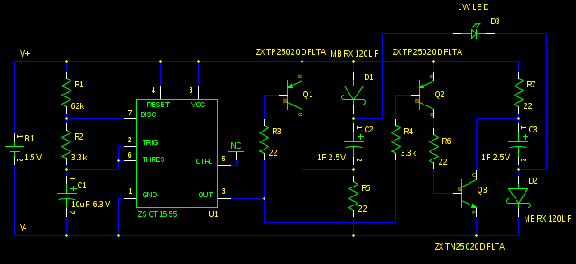
and pulse transistors in a voltage tripler arrangement. Here is how I
expanded the idea to produce a circuit that would flash two high power
LEDs at once:
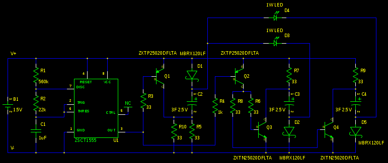
This is more or less the same thing as described in the previous
post. C4 and associated components just provide another branch for the
extra LED. The common branch through C2 needs twice the charging
current so R10 was added. I spent some time exploring the idea of
using two supercaps with low internal resistance and then using 1 ohm
resistors to limit the current through the two LEDs. Unfortunately
very small differences in forward voltage caused great differences in
LED brightness. I then said the heck with it and
more or less duplicated the circuit resulting in the use of four
supercaps. That would not fit in the available board area. The three
supercap solution was the compromise. I couldn't see any reason not to
keep using the low internal resistance supercaps (other than the
larger size) so the 1F (0.4 ohm) supercaps are now 3F (.09 ohm)
supercaps. This allowed the increase of the charging resistors from 22
to 33 ohms for more or less the same pulse current. The other 22 ohm
resistors were changed to 33 ohm just to eliminate the extra component
value.
In the previous post I claimed that there was something wrong with the
description of the timing components on the datasheet for the ZSCT1555
timer. I now withdraw my scurrilous accusation. The problem was with
my understanding of the non-ideal operation of the device at 1.5V. The
new values of R1, R2 and C1 result in flashes of 50ms at a rate of 1
per second. The capacitor is now a 1uF ceramic that fits on a 0805
footprint.
With a fresh battery this circuit produced pulses of about 0.4A
through each LED. When the battery is at 1V I would expect the current
to be about a quarter of that. The system will enter "infinite battery
life" mode with the battery at 0.83V. There is no reverse battery
protection here. Tests revealed that on a reverse battery the only
component that takes abuse is the 555 timer. I think the package
should be capable of dissipating the excess power. It did get pretty
hot. Because of the larger supercap value the system takes a
noticeable length of time to come up to full brightness when the
capacitors are uncharged. I consider that pretty cool. Unfortunately
the capacitors retain their charge quite well over time.
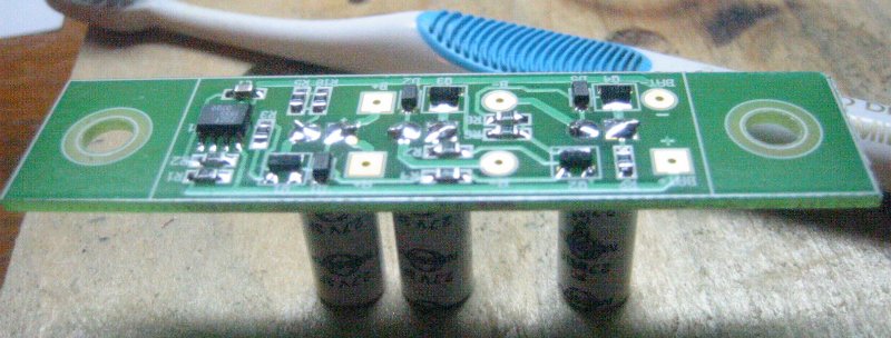
I designed a single sided board to mount on the traditional bicycle
water bottle cage mount (5mm bolts, 65mm spacing). The assembled board
looked like this:
The gEDA
files: Schematic
Layout
The design files: Gerbers
Postscript
PDF
Most of the board was done with 0.5mm lines and spaces with 0.35mm
lines and spaces where needed. As a result it should be realizable
with the toner transfer method. Here are the mirrored copper layer
images. Note that the board is 79.75mm by 19mm.
Mirrored copper: Postscript
PDF
I sent my board out to get
made. Here
are the files I sent. The company
was Olimex. You
have to edit the readme.txt file before you send these files off to
Olimex. This approach gets you 10 boards.
Pretty much any super/ultra cap will work here as long as the internal
resistance (ESR) is reasonably low. Higher ESR means less charging
current and a dimmer flash. Adjusting the value of the charging
resistors (R5, R7, R9, R10) downward can be used to compensate. Keep
in mind that increasing ESR is the major failure mode for supercaps
over time so you normally are better off starting with a low
value. Pretty much any 1 Watt LED will work as long as the forward
voltage is in the neighbourhood of 2.5V . The transistors are special
in that they must be capable of switching 1-2A with a low saturation
voltage.
Here is a parts list:
2       ZXTN25020DFLTA          NPN low sat volt pulse transistor sot-23 (diodes inc)
2       ZXTP25020DFLTA          PNP low sat volt pulse transistor sot-23 (diodes inc)
1       ZSCT1555N8TA            low volt 555 timer so-8 (diodes inc)
3       MBRX120LF               1A Schottky Diode sod-123 (Micro Commercial)
1       C0805C105K8RACTU        ceramic cap 1uf +-10% x7r 0805 (kemet)
3       ESHSR-0003C0-002R7      3F .09ohm supercap 3.5mm lead spacing (nesscap)
1       LTPL-P011A              1W amber led (Lite-On)
1       LTPL-P011R              1W red led (Lite-On)
1       2173                    steel C cell holder (keystone)
These part numbers were findable
on Digi-Key at the time of this
post. Normally you do not get things like 1 Watt LEDs from an
electronic distributor like Digi-Key. You can usually get better prices
elsewhere for small quantities. I just wanted to show an example of
the LEDs I ended up using.
Here is what I did for mounting:
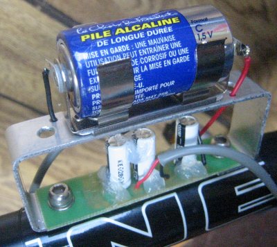
I suppose I could be accused of flaunting my geekiness here. I mostly
do stuff like this to attract the groupies. Social aspects aside, if
you live in a more hostile and/or corrosive atmosphere than I do you
might want to do a bit more with the enclosure ... such as actually
having one I mean. There is no switch, the battery is removed (or just
moved) when the flasher is not in use. If the bike is locked up
outside the battery ends up in a pocket. Any time the bike is in use
the battery is in place. That is just where I keep it.
The silicone sealant seen in the picture is intended to dampen the
vibrations of the capacitors to prevent lead breakage.
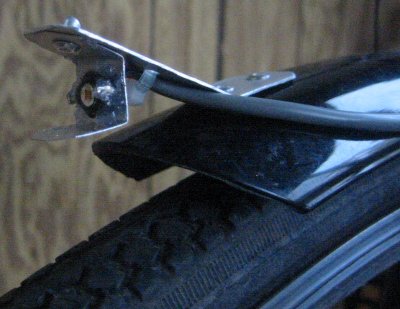
Here is what I did to mount the red LED on the rear:
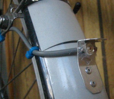
This is attached low on the read fender. This demonstrates an
advantage to centralized electronics I guess. You can put the actual
light emitters pretty much anywhere. The overhang was intended to make
a shade for people who are close to the back of the bike. It didn't
really work. It also protects the soft silicone lens of the LED. I was
told by a fairly LED adverse friend that the flashes were not that
bothersome. I think that is because the LED is mounted low to the
ground.
Here is what I did for the amber LED on the front:
This is mounted on the most forward extreme of the front
fender. Having a bright flashing light on the front of a bike is a bit
of a problem in that the rider has to be shielded from the flashes. I
made a reflector out of some shiny aluminium flashing in an attempt to
direct the light in line with the rider away to the front. It mostly
works but the top reflector directs some light onto the tire and the
road. Fortunately the tire is not all that reflective and the road
is far away. If I decide later that that light bothers me I will
blacken the offending part of the top reflector. Mounting the LED
relatively low like this produced an unexpected benefit. It greatly
reduced the flashing reflective sign effect.
These types of LEDs are often sold with a combination heat spreader
and terminal board. We don't need any sort of heat sink for this
application so I just soldered the bent up leads and glued the bare
LED in place with some silicone sealant. This flasher system is quite
insensitive to voltage drops in the wiring. Drops just make the
flashes a bit dimmer and the battery last a bit longer. As a result
I used 22 gauge wire to hook everything up.
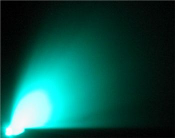
Here is the best I could do in terms of photographing the working flasher system:
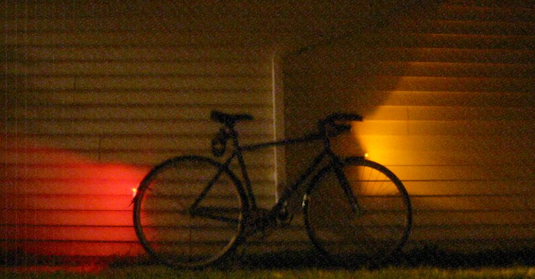
For those that can relate; this was taken at F2.8 and ASA 400. This
shows a single flash. In terms of sending light in all possible
directions we are doing quite good. Too good really, a lot of
the light ends up either in space or on the ground. Better optics
could help here but those optics would have to be larger than what I
have now. Fortunately we have quite a lot of light available to waste.
Speaking of waste, you can adjust the brightness of the flashes by
adjusting the charging resistors (R5, R7, R9, R10). Reducing them to
15 ohms would get you up to into 0.9A pulse range. I am fairly certain
that the resulting system would be reliable. It would however drain
the battery more than twice as fast. I don't think it would really get
you any more attention (at least of the positive kind).
To speed up the flash rate you can reduce the value of R1. Halving the
value of R1 would get you a pulse rate of 2 per second and a flash
brightness of half at more or less the same battery consumption. The
brightness could be restored by halving the value of the charging
resistors (as mentioned in the previous paragraph) at the cost of
twice the battery drain.
Speaking of batteries, this system would work well with a NiMH
cell. In fact it would provide a more or less constant voltage/light
output over the useful battery life. A NiMH cell has a high current
capacity so a NiMH AA cell charged every week or so would likely be
optimal.
I looked up the local laws with respect to bicycle lighting to try to
determine if a front and back flasher system is legal. As far as I can
determine it is not. I don't think anything someone might actually use
for lighting in this century would be. It has been a long time since
the laws were updated. I guess I'll just have to live with the
uncertainty. Around here the only reason law enforcement does not
spontaneously do something like hand out a safety award when a
bicycle/rider combination is seen emitting light at night is because
they are afraid they might be up to something.
The other research inspired by this project was night time bicycle
safety in general. From my experience a bright flashing light on the
front of the bike pretty much eliminates the common case of collisions
caused by cars turning left across the path of the bike. The other
common collision occurs when a car pulls out of a side
street/driveway. I have often seen a driver glance in my direction
between the flashes before deciding to go. This could be expected to
reduce the problem to the fully stealthed bike/rider
case. Unfortunately there is a complication. At some point during the
manoeuvre the driver will see the next flash in their peripheral
vision. Then their behaviour becomes impossible to predict. One of
three things will happen:
- They will slam on the brakes.
- They will hit the accelerator.
- Those driving at the very edge of their ability will go into
overload mode. This will produce a situation where there is a
driverless car on the road for a time.
A constantly illuminated headlight would help with this so I have to
acknowledge that such a thing is still a good idea no matter how
bright my front flasher is. Having said that, I think that I will still
often find myself with just the flashers. History has shown that it is
too much to ask that I maintain much in the way of lighting over the
long term. I can however manage a single battery. That simplicity is
the greatest advantage of a system like this in my opinion.
posted at: 14:57 |
path: /ledlight |
permanent link to this entry
Wed, 04 Aug 2010
Once upon a time, someone invented a solid state light source called a
light emitting diode (LED). Sometime after that a company called
National Semiconductor created an integrated circuit (IC) called the
LM3909 that flashed a LED.
The LM3909 was considered a very exciting thing in spite of the fact
that flashing a LED was pretty much all the LM3909 did. It did not
produce particularly bright flashes. It did not even flash the LED all
that quickly. It would however flash a LED for a very long time (years)
from a single 1.5V cell. That was enough.
This was something new in the world. The LM3909 showed how profoundly
different a light source the LED was compared to everything that had
come before. People that did electronics for fun absolutely loved the
LM3909 for providing this insight. At one time you could buy a LM3909
in pretty much any large shopping mall in North America (the ones
containing a store called Radio Shack). Combining a LM3909, a
capacitor and a battery just to watch a LED flash is something that
pretty much everyone of my generation with an interest in electronics
has done at one time or another.
The LM3909 did something sort of clever. A voltage of 1.5V was not
enough to cause one of the red LEDs of the day to emit light. The
LM3909 would charge up a several hundred uF capacitor to a significant
fraction of the 1.5V battery voltage. It would then force the
capacitor to be in series with the 1.5V power source causing the LED
to light until the capacitor discharged. The capacitor was charged
through a couple of resistors that drew relatively large currents when
the capacitor was forced into series mode. To get reasonable
efficiency the resistor values had to be on the larger side which
limited the flash rate to something like once a second.
In the late 90's, I was enduring an entire team of people who were
attempting to teach me undergraduate engineering math. This caused me
to yearn for the life I had left behind (electronics). Due to the
nature of the Electrical Engineering program I got to take my bicycle
home in the dark fairly often. Once a woman in a van pulled over and
told me a story with a very unhappy ending. It was about her friend
who shared with me a love of stealthy bicycle travel. My thoughts
naturally turned to lighting. Lighting involving electronics pretty
much leaves some sort of LED flasher.
At various points during the ensuing project people would make the
helpful suggestion that I could in fact just buy a bike
flasher. I suppose those same people would suggest that a Jedi Master
could hop into the land speeder and go pick up a light sabre. I didn't
want just a bike flasher. I wanted the bike flasher. ... and
well, the LM3909 was not it. It was power efficient at the cost of a
very weak flash. I was sort of disappointed.
I still wanted to be able to use a single 1.5V cell so I used the idea
of using a capacitor as a voltage multiplier as seen with the
LM3909. I found that a 1000uf capacitor made for a reasonable flash. I
wanted to use 3 LEDs with good lenses (10mm) adjusted to produce a fan
of light directed down the road and somewhat to the sides. I just did
not have enough light available that I could waste it. I eventually
ended up with a single large power transistor switching individual
1000 uF capacitors for each LED. That was 3 amber LEDs and 3
capacitors on the front of the bike and 3 red LEDs and 3 capacitors on
the back. I had to look to find some sort of convenient oscillator
that would run on 1.5V (really 1V). Turned out that the LM3909 was
ideal for the job and was used as the timing source. Sometimes you
just can't avoid using the LM3909.
The flasher system was quite bright and was visible even on cloudy
days. It served me well up to the point that the bicycle it was
attached to was stolen from outside a post-university workplace. There
was no on-off switch, I simply put a C cell in a battery holder on the
bike frame. The battery life was pretty much perpetual. I didn't
really care if I forgot and left the battery installed. I could have
used a smaller/lighter power source but I do not like having to think
about changing batteries.
We now draw a bit nearer to the actual point of this post... While
investigating the present state of high power LEDs for
a circadian
light fixture project I spent some time wondering what a flasher
using a high power LED would be like. I had felt limited by the amount
of current I could blast the LEDs of the late 90's with. I was pulsing
the LEDs with something like 100 mA. A 1W LED is rated for 350mA and
can be pulsed to .5A-1A. They are also more efficient at converting
electrical power to light. In particular I wanted a flasher bright
enough to be seen in a urban streetlight environment from all
directions.
I wanted to be able to retain the single C cell power source even if I
ended up with a lot less battery life. Now, it turns out that .04
seconds is a kind of sweet spot for flash duration when dealing with
human vision. For a given available optical energy, putting that
energy into a .04 second flash produces the greatest perceived
brightness. Doing the capacitor trick as before got me a capacitor
value of around 0.22 Farad for a reasonable .04 second flash. That is a
big capacitor. Fortunately there has been a recent technology
breakthrough in the form of what are often called supercapacitors. I
really needed .022 Farad with a low internal resistance
(ESR). Contemporary supercaps do not roll that way. I could get a much
larger value than I needed with a low ESR but that would make for a
really large pulse. In the end I was still able to use the supercap to
multiply the voltage of the battery but I had to do it a different way
than the venerable LM3909 did.
The LEDs I was pulsing way back when had a forward voltage drop of
around 2V. Typical high power LEDs are 2.5V for red and amber and 3.5V
for green and blue/white. OK, goodbye to green and blue/white
then. There is still a problem with red and amber. If we are only
doubling the voltage the battery can only discharge to 1.25V
(2*1.25V=2.5V). Dry cells are considered used up at about 1V. We are
losing half the battery life. OK then, hello second supercap. Now we
can triple the voltage. That does cause a pretty severe hit
in terms of efficiency. Since there are no inductors here all extra
voltage gets lost someplace in a resistance. The doubler has a maximum
possible efficiency of 2.5V/(2*1.5V)=0.83 and the tripler comes out at
2.5V/(3*1.5)=0.56. Still, 56% efficiency with twice the battery life
available is significantly better than 83%. We also need enough extra
room to charge the capacitors with resistors. So the tripler is the
way to go here. I will leave it as an exercise to come up with
something better using an inductor.
I still needed a timing source. The LM3909 is now discontinued (sniff)
but you can get 555 timers designed to run off of a single 1.5V
cell. I used the one from Zetex. Here is the schematic:
Here is a list of important parts used for the prototype (these were
the ones in stock at Digi-Key at the time of the order):
1       ZXTN25020DFLTA          NPN low sat transistor sot-23
2       ZXTP25020DFLTA          PNP low sat transistor sot-23
1       ZSCT1555N8TA            lo volt 555 timer so-8
2       MBRX120LF               1A Schottky Diode sod-123
2       B0810-2R5105-R          1F supercap
1       LTPL-P011A              1W amber led
1       BHCL                    plastic C cell holder
1       9081CA                  so-8 proto board
U1 is just a 555 timer so I will not bother explaining how it works
here. The values of R1, R2 and C1 gave a pulse length of 0.06 seconds
and a period of 1.1 seconds with the prototype. Close enough I
guess. By the way, the Zetex data sheet for the part seemed actively
misleading. I had to figure out the timing (which is different from a
normal 555 timer) on my own. The circuit formed by D1,C2 and R5 is the
same thing as the circuit formed by R7, C3 and D2 (just turned over)
so I will mostly just discuss one of them. C3 is charged during the
non-pulse time through Schottky diode D2 and R7. The Schottky diode is
quite over specified here in terms of maximum current. I was looking
for a diode with low forward voltage at only 30mA. This one managed
about 0.2V. Note that capacitor C3 never gets charged up to 1.5V. It
only charges as much as is needed to fire the LED. That is because the
RC time constant of C3 and R7 is relatively long at 22ohm*1F=22
seconds. This time constant means that the flasher actually needs to
warm up over the course of 10 seconds or so before it reaches full
brightness.
The LED fires when pin 3 of U1 goes low. Q3 is turned on through Q2
and drags the positive end of C3 to the V- rail. D2 is reverse biased
and turns off. Let us assume that the V- rail is 0V. Then the negative
end of C3 (and the negative end of the LED) is now as little as
-1.5V. Q1 does the same sort of thing to C2 with respect to the V+
rail at +1.5V to drive the positive end of the LED as high as
+3V. Thus potentially the LED could have as much as 4.5V across
it. This would be too much voltage for the LED. The RC time constant
mentioned previously prevents this excessive voltage at the LED. There
simply isn't enough time for R7 to change the voltage of the capacitor
any significant amount before the next pulse. Eventually an
equilibrium is reached with the amount of charge going into the
capacitor during charging time coming out during the LED pulse
time. In practise the voltage across the capacitors is exactly enough
to add together with the battery voltage to make up the LED
voltage. It tends to be higher than expected because of the internal
resistance of the capacitors when the led fires. The capacitors are
rated at .4 ohms internal resistance and showed a drop of 0.2V with a
0.5A pulse. Lower internal resistance is better but makes for a more
expensive supercapacitor.
And speaking of things that drop voltage, the transistors used here
are special in that they drop very little voltage when turned on. They
need to be driven hard to do this. For the old flasher I ended up
using a transistor in a huge TO-220 package. As these transistors come
in SOT-23 packages this ends up being a sort of technology improvement
as well.
The LED current here is limited quite accurately by the combination of
the value of R7 and the duty cycle of the pulse. This is possible due
to the large value of the supercapacitor and is a very nice
result. Unfortunately as the battery voltage drops the voltage across
R7 drops. That means that the LED gets dimmer over time. With the
prototype the combination of extra voltage available due to tripling
combined with the internal resistance of the capacitors produced a
situation where the LED brightness was still a bit more than a third
of the full voltage brightness when the battery hit 1V ("dead"). That
is also a nice result. This could be improved by finding a less
voltage sensitive way to charge the capacitors.
Here is what the prototype looked like:
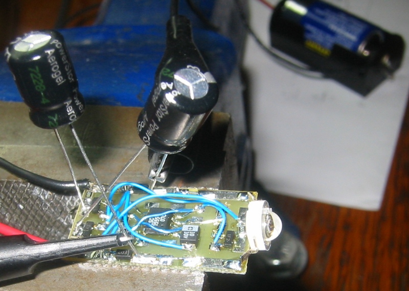
With a new battery it produced pulses of about 0.5A. The light output
is really intense ... which is good. I think that battery life should
be something like 100 hours with a C cell and 150 hours with a D
cell. The front and back dual flasher I now hope to build should thus
get about 50 hours on a C cell.
This flasher suffers from a problem I refer to as the infinite battery
life syndrome. You often see bicycle flashers in the wild producing
barely perceptible light output. I think that is caused by a
combination of human perception and the characteristics of LEDs. As
the battery voltage gets closer and closer to the LED forward voltage
the current decreases and as a result the battery life
increases. Eventually the current gets down into the microamp range
but the LEDs are still showing light. Since people are really bad at
judging brightness there never comes a time where it is obvious that
the battery needs to be changed. Since this is safely critical
equipment I do not think this is good design. Presently the prototype
is happily producing 63 mA (0.07V across R5 while charging) pulses at
a battery voltage of 0.83V after running steady for a week and a half
and now seems fairly stable. I guess one could add a voltage detector
and do something on low battery voltage. I have no idea what this
something should be.
I know that 1 second period flashers are considered with some disdain
in some quarters. The issue is that it makes it difficult for
observers to infer the speed and direction of the bicycle. I can rebut
this from experience as I have used such a flasher for some years. On
a totally dark street there might be an issue but in an urban
environment if you can draw attention to yourself there is almost
always enough light to follow the path of the bicycle/rider
afterwards. This is especially true if the bicycle is liberally
plastered with reflective tape as mine is. Since attracting attention
is important it seems reasonable to throw out as much light energy as
possible during the pulse. The best way to do this is to pulse as
infrequently as is practical.
The stuff about the pulse energy brings up another objection. Some
people feel that very bright flashers are obnoxious. The amount of
light intensity produced by my prototype during the pulse is more or
less the same as the light intensity produced for a much longer time
by the flash of a automotive signal light. The reason it is annoying
is because the light comes from a very small area. The problem is that
it is impossible to separate annoying from attention attracting. One
implies the other. From my interest in circadian light I know that
even very bright red LEDs can only zap one photoreceptor (amber is
pretty much one and a half). There are three types left so I do not
think it is possible to night blind someone with red/amber LEDs. So
given that, the concise response is:
Annoying? Good! I wanna live...
posted at: 21:39 |
path: /ledlight |
permanent link to this entry
Mon, 26 Apr 2010
The small area of LED light emitters makes it somewhat challenging to
use them effectively in low level lighting applications. The light is
hard to shade and diffuse efficiently. In the past I have used light
coloured ceilings and walls as diffuse reflectors. This works fairly
well but it can be a problem avoiding a bright area on the
wall/ceiling where the light is
mounted.
Here
is a description of a light I built that physically moves the light
emitters away from the wall to deal with this issue. This works but
the resulting fixture is quite large.
The ideal angle of the wedge of light from a wall mounted fixture is
something a bit under 90 degrees. We want to avoid illuminating the
wall behind the fixture while preventing people from seeing the small
bright emitters directly. We also do not want a lot of light on the
ceiling closest to the fixture as this tends to make a bright spot,
particularly if the fixture is close to the ceiling. The raw LED chip
itself emits light from a flat surface. This means that the light
distribution tends to be proportional to the cosine of the angle from
the normal. Cutting this distribution in half would produce a fairly
good light distribution for the application. That could be done by
adding a horizontal reflector. Since we have no need for optics other
than the reflector we might as well use surface mount LEDs and make
the fixture small.
I wanted to experiment with monochrome light as we are targeting night
vision here. This plot:
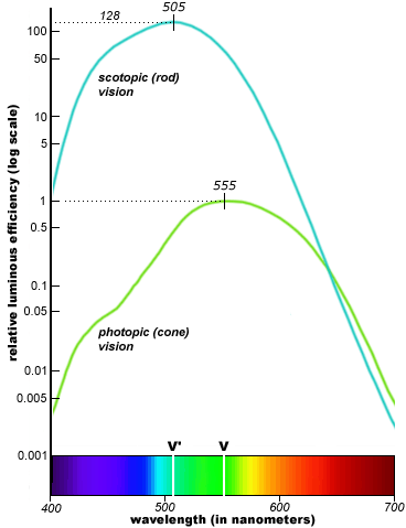
from here
suggests that the best wavelength for night (scotopic) vision would be
505 nm. That by coincidence is the wavelength that is perceived as the
North American traffic signal "green" colour. As a result LEDs that
emit this odd wavelength are relatively easy to find. The colour ends
up being sort of a cyanish green. Light with a wavelength of 505 nm is
fairly active
as circadian
light but the light levels achieved here are much too low to be
disruptive.
My thinking up to this point inspired me to go out and
buy these
from here. I ended up with the larger
1206 packages because the supplier I ordered from would only provide
the wavelength I wanted in that size. The extra width (1.6mm) ended up
not being a problem and they were easier to handle than the 0805
packages I normally prefer for hand made surface mount based
prototypes.
I spent some time planning to use a thin sheet of stainless steel as a
reflector until I stumbled on this at a local home improvement store:
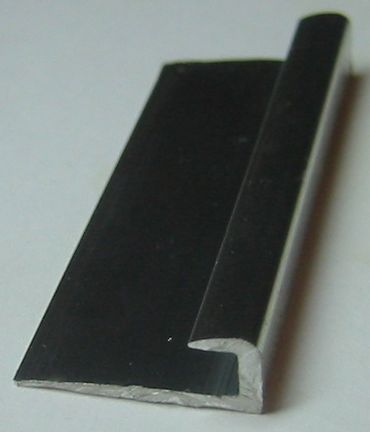
It was originally intended as an edging for a counter top. It was made
out of a shiny alloy and was close to the desired shape. It comes with
a prefabricated wall shade in the form of the overhang.
The use of the surface mount devices pretty much mandated the use of the PCB. Rather than measure anything I made a drawing at 5X scale:
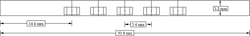
and then printed it at 20% to use as a guide. Much to my surprise the Xfig program on Linux got it exactly right with no fiddling. That's not all that expected for a mere figure creation program. Here is the drawing in various formats:
fig,
postscript,
pdf,
svg,
png.
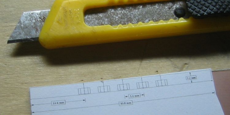
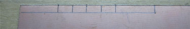
A sharp tool was used to transfer the dimensions from the 1X scale drawing to the copper:
followed by a layout:
followed by some use of a cutting disk:
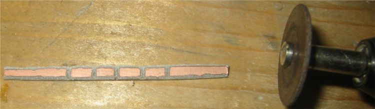
Note that the edges of the copper have been ground off to prevent
shorts through the metal reflector. I just dragged the cutting disk
along the sides. A more appropriate tool would make for a straighter
edge.
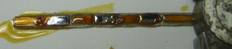
I first applied liquid flux to the PCB. This is probably optional for
such a simple assembly but I had it available and it did make things
easier. A popular method of hand soldering surface mount devices starts
by adding solder to just one pad. In my case this meant I would first
add solder to each alternate area of copper like this:
Then the device is moved into position and held in place with
something like a round toothpick. Heat from a soldering iron is
applied to the solder (but not directly to the device) to sweat solder
the device in place. Then it is fairly easy to solder the other
pins. Once the device is well secured the original pin can have solder
added if needed. This was the scene after soldering was complete:
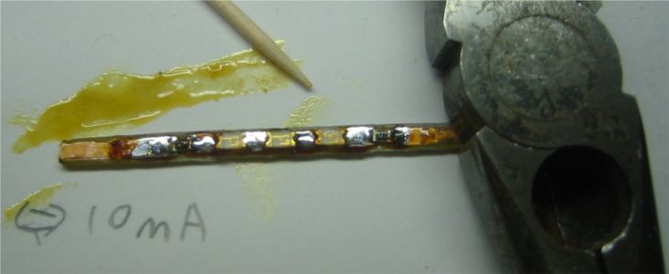
I have ended up with 3 LEDs and 2 resistors. When I made the drawing I
was enough of an engineer to want to cover the case where 4 LEDs were
required to make up the voltage. The idea was to just skip one cut for
the 3 LED case. When I made the board I was apparently enough of a
technician to be compelled to make things as shown on the
drawing. Thus I managed to make a classic error involving an ambiguous
drawing in a way that normally requires two people. Using 2 resistors
solved the problem in the assembly phase which meant I had also
achieved pointless symmetry which is another sort of classic
error. There is probably some insightful observation on the human
condition available to me here but it escapes me.
I picked a LED current of half the normal specification based on the
hope that it might increase the lifetime of the fixture. I have no
idea if that makes sense with LEDs. Heat might not be an issue. LED
manufacturers like to quote a lifetime of 100,000 hours (11 years)
which really just means they think their product might last a long
time. With a target current of 10 mA we end up with
(12V-(3.2V*3))/0.01A = 240 ohms of resistance. I ended up using two
110 ohm resistors.
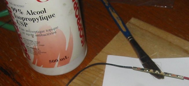
After soldering the wire connections and cleaning off the rosin based
flux with pure isopropyl alcohol I was done with the electrical
assembly:
I used a small amount of RTV silicone sealant to glue the board in
place in the reflector. The board would not stay where it was supposed
to go. I ended up using the weight of the wires to keep it in place:
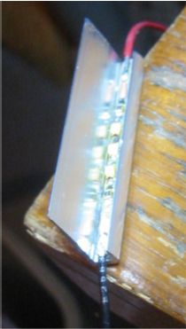
The preceding image shows that the reflector is quite a lot wider
than would be required just to reflect the light from the LEDs. The
idea was to prevent light from escaping from the ends of the channel
without any extra fabrication. This worked but the channel itself was
still a bit bright where it could be seen on the ends.
Testing the light distribution against a white surface showed some problems:
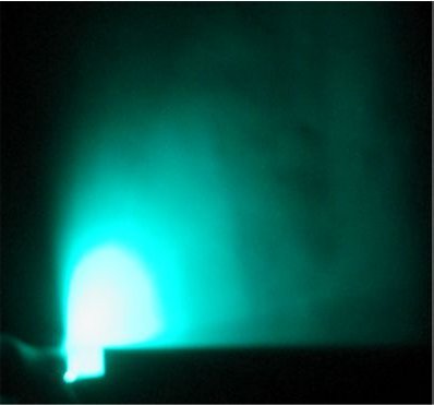
To prevent light from projecting below the horizontal plane the
assembly had to be tilted back towards the LED side. This is
inconvenient for the eventual installation of the fixture and caused
two other problems. The largest amount of light was going more or less
directly up to the ceiling above the fixture creating a bright
spot. The other problem was that a significant amount of light was
finding its way to the wall directly behind the fixture which created
another bright area. Blackening the top of the channel helped but I
eventually took a different approach and bent the end of the reflector
up like this:
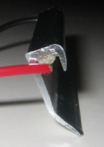
The edge of the reflector is bent up enough to be in the same plane as
the top of the channel. This means that there is no light projected
below the horizontal plane when the fixture is sitting flat against a
horizontal surface. The result was:
This is much better. I consider the design complete.
Next I'll go into the various thoughts and observations that came out
of this activity...
When using monochromatic light even illumination can create a
situation that destroys visual information. The light from the
designed fixture is very uniform. Evenly illuminating large areas of
the ceiling results in a situation related to an
outdoors whiteout
condition. Objects are still visible but with little detail. I suspect
that this would only be an issue in rooms small enough to allow a
single fixture to evenly illuminate the entire ceiling. A fix is to
move the fixture closer to the ceiling to produce sharper shadows at
the cost of a more intense hot spot.
The Homo sapiens sapiens set depend on visual transitions in their
peripheral vision to help with things like walking around. The sharp
vertical light transition produced by the reflector means that a
strong cue should exist for orientation and balance. This artificial
horizon effect might end up being the more important visual
information. This system is after all intended to improve
navigation. I am not sure how well this actually works at low light
levels. There is probably a research opportunity here.
An important performance feature of a low level lighting system is the
length of time it takes for vision to adapt enough to navigate after
the high level lighting is turned off. Testing this produced a result
that initially seemed odd. It seemed that the nighttime vision system
(rod based) was adapting significantly faster than the daytime vision
system (cone based). I would see a monochrome image before I could perceive
the colour of the light. This lag was something like 5 seconds. The
oddness here came from the impression that nighttime vision takes a
much longer time to adapt to darkness than daytime vision. Some
research revealed that this isn't really true in general. It turns out
that the traditional way to check the time it takes people to adapt to
the dark is to expose them to really bright light for a long time and
then plunge them into complete darkness. This presumably is to
simulate the common situation where one is walking along in a sunlit
meadow before falling into a fast moving underground river. In more
reasonable transitions from light to dark it is the nighttime vision
that kicks in first
(Ref, See
Figure 2). At the light levels I am using the effect would be close to
the maximum. The daytime vision system has to adapt to a level close
to the daytime minimum while the nighttime vision system only has to
adapt to a light level 100 times higher than the nighttime
minimum. The transition is driven harder for the nighttime
system. This I think strengthens the contention that 505 nm is the
magic wavelength for low level lighting.
Since the edge of the reflector is to be bent up it might make sense
to cut the reflector in such a way as to allow the bent up part to
shade the bright ends of the channel. In other words, the reflector
could be cut off at an angle to make the LED side shorter than the
bent side. This could also hide associated wiring.
Light fixtures that point upward accumulate dirt. This creates a
maintenance issue. For some applications it might be better to put the
light sources below eye level pointing downward. Hallways and
walkways are sometimes lit this way.
Blue LEDs at 470 nm are fairly effective for nighttime vision but are
a lot less visible to daytime vision than 505 nm LEDs. This might make
blue LEDs preferable where it is important for the night lighting to
be invisible during the day.
The next step is to make some of these and deploy them around the
house to try out the low level lighting lifestyle for myself. I should
be able to hide the fixtures on the top of door and window
frames. This will make it possible to hook the wires up into the attic
for an easy installation. I will report on the results when and if
there are any.
EDIT: proceeding -> preceding
posted at: 15:49 |
path: /ledlight |
permanent link to this entry
Thu, 18 Feb 2010
I seem to be stuck on the low level lighting thing. An advantage to
not working is not having anyone to tell me to get back to work...
Here is an
approachable introduction to modern colour vision theory. It helped me
a lot. The rest of the site (watercolours) is a bit too technical for
me but I think I now know what to expect when I mix single colour
LEDs.
For my bathroom night light I now think that just green and red LEDs
would of worked fairly well. I could of balanced them to give some
sort of yellow. A problem would occur if the colour was exactly the
same as the perceived light colour. It would not be visible against
white. The 3rd colour in between removes that ambiguity. That is
assuming that the green and red LEDs do not balance out to the in
between colour. The apparently excessively bright green LED is thus a
feature as it moves the balance point well away from the yellow LED
wavelength.
Another possible problem with just using green and red (or blue and
red) is that you would end up with more green light. Green (and blue)
can blind night vision when not used in moderation. I now think of my
bathroom night light as primarily yellow with a bit of some other
wavelengths thown in to allow some colour discrimination.
posted at: 17:13 |
path: /ledlight |
permanent link to this entry
Wed, 27 Jan 2010
Some wisdom came out of my night light projects. I'll share that here.
Are light emitting diodes ready for prime time residential lighting?
That question is surprisingly controversial. I am not really sure
myself about the answer to the general question. I am sure that
for low level lighting LEDs entirely rule.
Up to this point in the history of the world there has not been a
practical and efficient way to make a small amount of light for a long
time. Incandescents are particularly
bad
for efficiency and life.
Electroluminescent
were the closest thing pre-LED era but they are an area emitter and
are thus hard to shade effectively. They also need high voltage
wiring.
The result of this is that the system of vision intended to allow
people to function at night is not really used by most people. People
can see at levels down to 0.01 lux. Typical residential living spaces
are lit to levels between 50 to 100 lux. That is as much as 4 orders
of magnitude more than the absolute minimum required.
It may be that we have hit a technological threshold. If low level
lighting is more practical then perhaps it will become more common. It
is interesting to consider how a hypothetical low level lighting
enthusiast would arrange the lighting in a house.
Let us first invent a specification. All living areas should be lit to
the level of moonlight on a clear night. One
source claims this is
.3-1 lux. Brighter would interfere with things like sleep. Darker
would mean a longish time to adapt after turning off a light. Tropical
moonlight would be a bit bright I think so let's aim for the lower end
of .3 lux.
For a 3m X 3m room we would have around 10m2 to illuminate. Lux is
lumens per square metre so to hit .3 lux we would need 3 lumens. LEDs
with an efficacy of 30 lumens/watt are available so our power budget
could assume around 0.1W per lamp. Since this is mostly best case I'll
double the assumption to 0.2W. It would likely take 7 of these lamps
to light my house. So the total power draw is 1.4W giving us a yearly
power consumption of 12 kW/h. That would cost me $0.72CAN a year.
The fixtures could be built in at time of construction. Retrofit would
be easy as you would only have to snake in something like alarm wire
to power the lights. The lights could be designed to run off the door
bell transformer. If instead you ran them off a small sealed lead acid
battery charged from a wall wart you could claim that you had
established a sort of residential emergency egress lighting system.
The proposed level of lighting would of course mostly serve for
navigating through the house. This would still simplify things. Most
rooms would not need any ceiling lights and associated
switches/wiring. Hallways and stairways would not need three way
switched lights.
In general safety would be greater at night. I used to fall over the
stool in my kitchen on a semi-regular basis before I installed my
always-on counter light. I did get quite good at it but it would be
unrealistic to think I would not eventually do it badly. The compact
fluorescent that lights my basement stairs sometimes likes to wait just
long enough for me to miss the top step before producing light after I
turn it on. A little bit of light would help there too.
Our house of the future would probably need some built in higher level
lighting. A ceiling mounted light for the dining room table is
nice. Vanity lighting for the bathroom mirror is essential to allow
the residents to maximize their apparent reproductive fitness. Kitchen
counters and the stove would need bright lighting. Pretty much the
rest of the lighting inside the house would be provided with lamps.
When one deals with lighting one is dealing with some fairly primal
stuff. I always need to turn on the main light in the bathroom before
having a bath. I think I am afraid to go in the dark water. Perhaps at
some level I am afraid of alligators. When fluorescent lighting become
popular people immediately started illuminating work spaces to some
almost insane levels. Legend has it that photographers of that era
used to have trouble believing the result of their light meter
readings. They were seeing outside daylight levels of lighting inside
buildings. A decade or so later "de-lamping" became popular when it
became fashionable to care about power consumption. My point is that
people like it when it is bright indoors and the brighter the
better. Perhaps low level lighting as a way of life will never become
popular simply because of that.
Here are some interesting/related links;
posted at: 22:37 |
path: /ledlight |
permanent link to this entry
Powered by PyBlosxom
