The ideal angle of the wedge of light from a wall mounted fixture is something a bit under 90 degrees. We want to avoid illuminating the wall behind the fixture while preventing people from seeing the small bright emitters directly. We also do not want a lot of light on the ceiling closest to the fixture as this tends to make a bright spot, particularly if the fixture is close to the ceiling. The raw LED chip itself emits light from a flat surface. This means that the light distribution tends to be proportional to the cosine of the angle from the normal. Cutting this distribution in half would produce a fairly good light distribution for the application. That could be done by adding a horizontal reflector. Since we have no need for optics other than the reflector we might as well use surface mount LEDs and make the fixture small.
I wanted to experiment with monochrome light as we are targeting night vision here. This plot:
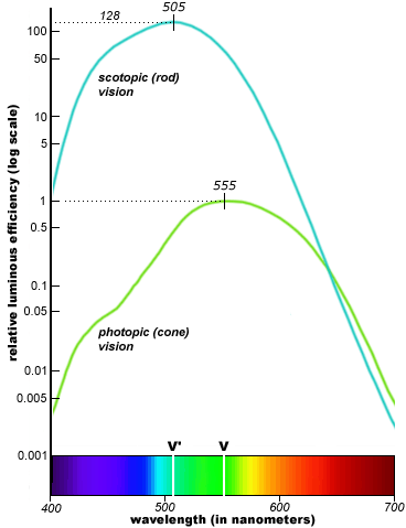
from here suggests that the best wavelength for night (scotopic) vision would be 505 nm. That by coincidence is the wavelength that is perceived as the North American traffic signal "green" colour. As a result LEDs that emit this odd wavelength are relatively easy to find. The colour ends up being sort of a cyanish green. Light with a wavelength of 505 nm is fairly active as circadian light but the light levels achieved here are much too low to be disruptive.
My thinking up to this point inspired me to go out and buy these from here. I ended up with the larger 1206 packages because the supplier I ordered from would only provide the wavelength I wanted in that size. The extra width (1.6mm) ended up not being a problem and they were easier to handle than the 0805 packages I normally prefer for hand made surface mount based prototypes.
I spent some time planning to use a thin sheet of stainless steel as a reflector until I stumbled on this at a local home improvement store:
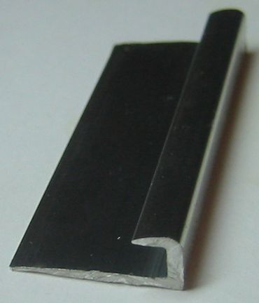
It was originally intended as an edging for a counter top. It was made out of a shiny alloy and was close to the desired shape. It comes with a prefabricated wall shade in the form of the overhang.
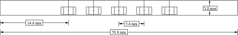
The use of the surface mount devices pretty much mandated the use of the PCB. Rather than measure anything I made a drawing at 5X scale:

and then printed it at 20% to use as a guide. Much to my surprise the Xfig program on Linux got it exactly right with no fiddling. That's not all that expected for a mere figure creation program. Here is the drawing in various formats: fig, postscript, pdf, svg, png.
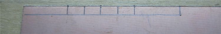
A sharp tool was used to transfer the dimensions from the 1X scale drawing to the copper:
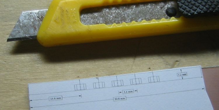
followed by a layout:
followed by some use of a cutting disk:
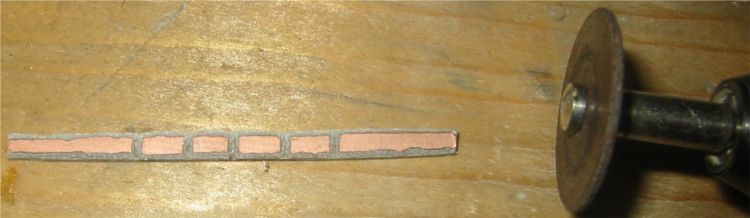
Note that the edges of the copper have been ground off to prevent shorts through the metal reflector. I just dragged the cutting disk along the sides. A more appropriate tool would make for a straighter edge.
I first applied liquid flux to the PCB. This is probably optional for such a simple assembly but I had it available and it did make things easier. A popular method of hand soldering surface mount devices starts by adding solder to just one pad. In my case this meant I would first add solder to each alternate area of copper like this:
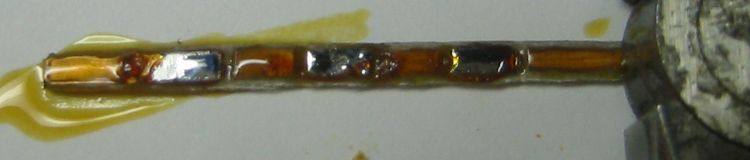
Then the device is moved into position and held in place with something like a round toothpick. Heat from a soldering iron is applied to the solder (but not directly to the device) to sweat solder the device in place. Then it is fairly easy to solder the other pins. Once the device is well secured the original pin can have solder added if needed. This was the scene after soldering was complete:
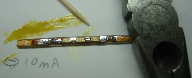
I have ended up with 3 LEDs and 2 resistors. When I made the drawing I was enough of an engineer to want to cover the case where 4 LEDs were required to make up the voltage. The idea was to just skip one cut for the 3 LED case. When I made the board I was apparently enough of a technician to be compelled to make things as shown on the drawing. Thus I managed to make a classic error involving an ambiguous drawing in a way that normally requires two people. Using 2 resistors solved the problem in the assembly phase which meant I had also achieved pointless symmetry which is another sort of classic error. There is probably some insightful observation on the human condition available to me here but it escapes me.
I picked a LED current of half the normal specification based on the hope that it might increase the lifetime of the fixture. I have no idea if that makes sense with LEDs. Heat might not be an issue. LED manufacturers like to quote a lifetime of 100,000 hours (11 years) which really just means they think their product might last a long time. With a target current of 10 mA we end up with (12V-(3.2V*3))/0.01A = 240 ohms of resistance. I ended up using two 110 ohm resistors.
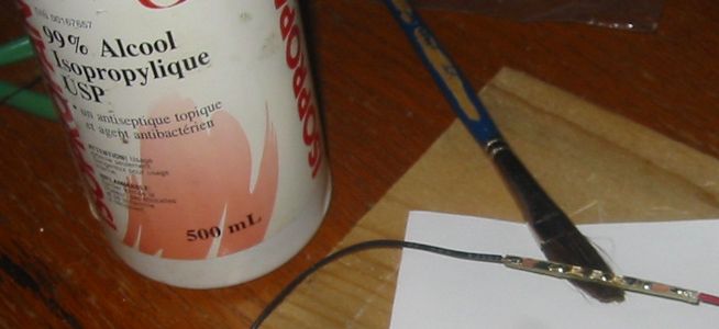
After soldering the wire connections and cleaning off the rosin based flux with pure isopropyl alcohol I was done with the electrical assembly:
I used a small amount of RTV silicone sealant to glue the board in place in the reflector. The board would not stay where it was supposed to go. I ended up using the weight of the wires to keep it in place:
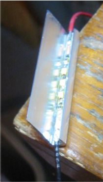
The preceding image shows that the reflector is quite a lot wider than would be required just to reflect the light from the LEDs. The idea was to prevent light from escaping from the ends of the channel without any extra fabrication. This worked but the channel itself was still a bit bright where it could be seen on the ends.
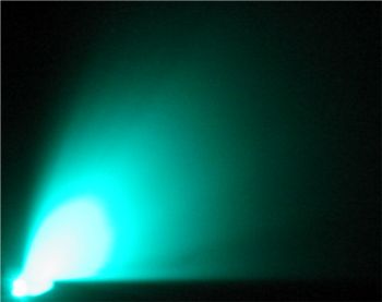
Testing the light distribution against a white surface showed some problems:
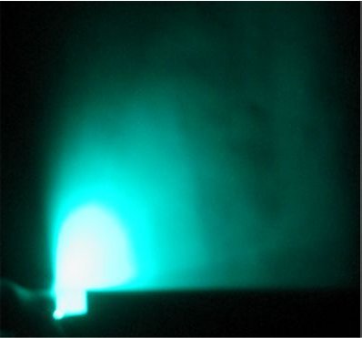
To prevent light from projecting below the horizontal plane the assembly had to be tilted back towards the LED side. This is inconvenient for the eventual installation of the fixture and caused two other problems. The largest amount of light was going more or less directly up to the ceiling above the fixture creating a bright spot. The other problem was that a significant amount of light was finding its way to the wall directly behind the fixture which created another bright area. Blackening the top of the channel helped but I eventually took a different approach and bent the end of the reflector up like this:
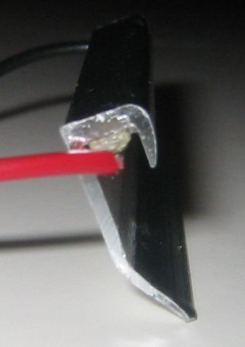
The edge of the reflector is bent up enough to be in the same plane as the top of the channel. This means that there is no light projected below the horizontal plane when the fixture is sitting flat against a horizontal surface. The result was:
This is much better. I consider the design complete.
Next I'll go into the various thoughts and observations that came out of this activity...
When using monochromatic light even illumination can create a situation that destroys visual information. The light from the designed fixture is very uniform. Evenly illuminating large areas of the ceiling results in a situation related to an outdoors whiteout condition. Objects are still visible but with little detail. I suspect that this would only be an issue in rooms small enough to allow a single fixture to evenly illuminate the entire ceiling. A fix is to move the fixture closer to the ceiling to produce sharper shadows at the cost of a more intense hot spot.
The Homo sapiens sapiens set depend on visual transitions in their peripheral vision to help with things like walking around. The sharp vertical light transition produced by the reflector means that a strong cue should exist for orientation and balance. This artificial horizon effect might end up being the more important visual information. This system is after all intended to improve navigation. I am not sure how well this actually works at low light levels. There is probably a research opportunity here.
An important performance feature of a low level lighting system is the length of time it takes for vision to adapt enough to navigate after the high level lighting is turned off. Testing this produced a result that initially seemed odd. It seemed that the nighttime vision system (rod based) was adapting significantly faster than the daytime vision system (cone based). I would see a monochrome image before I could perceive the colour of the light. This lag was something like 5 seconds. The oddness here came from the impression that nighttime vision takes a much longer time to adapt to darkness than daytime vision. Some research revealed that this isn't really true in general. It turns out that the traditional way to check the time it takes people to adapt to the dark is to expose them to really bright light for a long time and then plunge them into complete darkness. This presumably is to simulate the common situation where one is walking along in a sunlit meadow before falling into a fast moving underground river. In more reasonable transitions from light to dark it is the nighttime vision that kicks in first (Ref, See Figure 2). At the light levels I am using the effect would be close to the maximum. The daytime vision system has to adapt to a level close to the daytime minimum while the nighttime vision system only has to adapt to a light level 100 times higher than the nighttime minimum. The transition is driven harder for the nighttime system. This I think strengthens the contention that 505 nm is the magic wavelength for low level lighting.
Since the edge of the reflector is to be bent up it might make sense to cut the reflector in such a way as to allow the bent up part to shade the bright ends of the channel. In other words, the reflector could be cut off at an angle to make the LED side shorter than the bent side. This could also hide associated wiring.
Light fixtures that point upward accumulate dirt. This creates a maintenance issue. For some applications it might be better to put the light sources below eye level pointing downward. Hallways and walkways are sometimes lit this way.
Blue LEDs at 470 nm are fairly effective for nighttime vision but are a lot less visible to daytime vision than 505 nm LEDs. This might make blue LEDs preferable where it is important for the night lighting to be invisible during the day.
The next step is to make some of these and deploy them around the house to try out the low level lighting lifestyle for myself. I should be able to hide the fixtures on the top of door and window frames. This will make it possible to hook the wires up into the attic for an easy installation. I will report on the results when and if there are any.
EDIT: proceeding -> preceding
posted at: 15:49 | path: /ledlight | permanent link to this entry