In a previous post I talked about a prototype 1.5V powered LED flasher capable of producing high pulse currents. The trick was to use supercapacitors and pulse transistors in a voltage tripler arrangement. Here is how I expanded the idea to produce a circuit that would flash two high power LEDs at once:
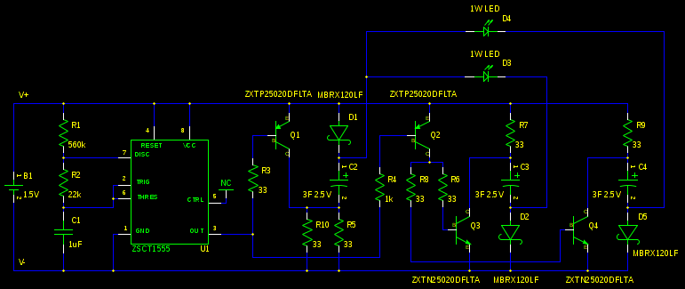
This is more or less the same thing as described in the previous post. C4 and associated components just provide another branch for the extra LED. The common branch through C2 needs twice the charging current so R10 was added. I spent some time exploring the idea of using two supercaps with low internal resistance and then using 1 ohm resistors to limit the current through the two LEDs. Unfortunately very small differences in forward voltage caused great differences in LED brightness. I then said the heck with it and more or less duplicated the circuit resulting in the use of four supercaps. That would not fit in the available board area. The three supercap solution was the compromise. I couldn't see any reason not to keep using the low internal resistance supercaps (other than the larger size) so the 1F (0.4 ohm) supercaps are now 3F (.09 ohm) supercaps. This allowed the increase of the charging resistors from 22 to 33 ohms for more or less the same pulse current. The other 22 ohm resistors were changed to 33 ohm just to eliminate the extra component value.
In the previous post I claimed that there was something wrong with the description of the timing components on the datasheet for the ZSCT1555 timer. I now withdraw my scurrilous accusation. The problem was with my understanding of the non-ideal operation of the device at 1.5V. The new values of R1, R2 and C1 result in flashes of 50ms at a rate of 1 per second. The capacitor is now a 1uF ceramic that fits on a 0805 footprint.
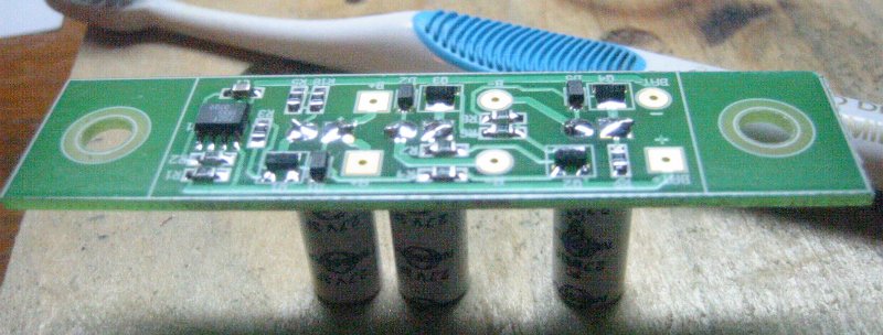
With a fresh battery this circuit produced pulses of about 0.4A through each LED. When the battery is at 1V I would expect the current to be about a quarter of that. The system will enter "infinite battery life" mode with the battery at 0.83V. There is no reverse battery protection here. Tests revealed that on a reverse battery the only component that takes abuse is the 555 timer. I think the package should be capable of dissipating the excess power. It did get pretty hot. Because of the larger supercap value the system takes a noticeable length of time to come up to full brightness when the capacitors are uncharged. I consider that pretty cool. Unfortunately the capacitors retain their charge quite well over time. I designed a single sided board to mount on the traditional bicycle water bottle cage mount (5mm bolts, 65mm spacing). The assembled board looked like this:
The gEDA files: Schematic Layout
The design files: Gerbers Postscript PDF
Most of the board was done with 0.5mm lines and spaces with 0.35mm lines and spaces where needed. As a result it should be realizable with the toner transfer method. Here are the mirrored copper layer images. Note that the board is 79.75mm by 19mm.
Mirrored copper: Postscript PDF
I sent my board out to get made. Here are the files I sent. The company was Olimex. You have to edit the readme.txt file before you send these files off to Olimex. This approach gets you 10 boards.
Pretty much any super/ultra cap will work here as long as the internal resistance (ESR) is reasonably low. Higher ESR means less charging current and a dimmer flash. Adjusting the value of the charging resistors (R5, R7, R9, R10) downward can be used to compensate. Keep in mind that increasing ESR is the major failure mode for supercaps over time so you normally are better off starting with a low value. Pretty much any 1 Watt LED will work as long as the forward voltage is in the neighbourhood of 2.5V . The transistors are special in that they must be capable of switching 1-2A with a low saturation voltage.
Here is a parts list:
2       ZXTN25020DFLTA          NPN low sat volt pulse transistor sot-23 (diodes inc)
2       ZXTP25020DFLTA          PNP low sat volt pulse transistor sot-23 (diodes inc)
1       ZSCT1555N8TA            low volt 555 timer so-8 (diodes inc)
3       MBRX120LF               1A Schottky Diode sod-123 (Micro Commercial)
1       C0805C105K8RACTU        ceramic cap 1uf +-10% x7r 0805 (kemet)
3       ESHSR-0003C0-002R7      3F .09ohm supercap 3.5mm lead spacing (nesscap)
1       LTPL-P011A              1W amber led (Lite-On)
1       LTPL-P011R              1W red led (Lite-On)
1       2173                    steel C cell holder (keystone)
These part numbers were findable on Digi-Key at the time of this post. Normally you do not get things like 1 Watt LEDs from an electronic distributor like Digi-Key. You can usually get better prices elsewhere for small quantities. I just wanted to show an example of the LEDs I ended up using.
Here is what I did for mounting:
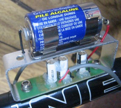
I suppose I could be accused of flaunting my geekiness here. I mostly do stuff like this to attract the groupies. Social aspects aside, if you live in a more hostile and/or corrosive atmosphere than I do you might want to do a bit more with the enclosure ... such as actually having one I mean. There is no switch, the battery is removed (or just moved) when the flasher is not in use. If the bike is locked up outside the battery ends up in a pocket. Any time the bike is in use the battery is in place. That is just where I keep it.
The silicone sealant seen in the picture is intended to dampen the vibrations of the capacitors to prevent lead breakage.
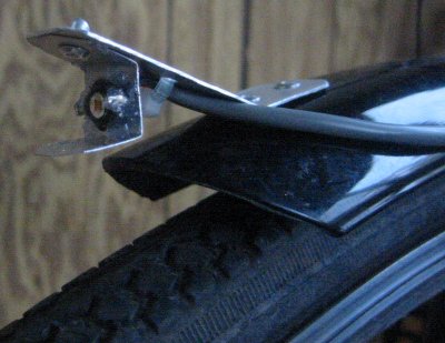
Here is what I did to mount the red LED on the rear:
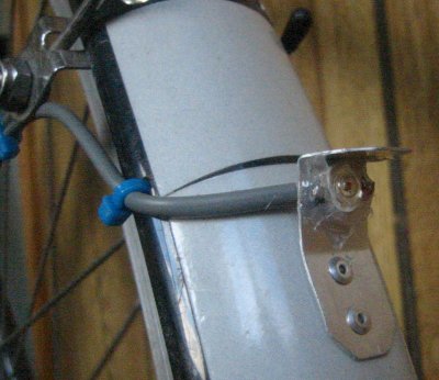
This is attached low on the read fender. This demonstrates an advantage to centralized electronics I guess. You can put the actual light emitters pretty much anywhere. The overhang was intended to make a shade for people who are close to the back of the bike. It didn't really work. It also protects the soft silicone lens of the LED. I was told by a fairly LED adverse friend that the flashes were not that bothersome. I think that is because the LED is mounted low to the ground.
Here is what I did for the amber LED on the front:
This is mounted on the most forward extreme of the front fender. Having a bright flashing light on the front of a bike is a bit of a problem in that the rider has to be shielded from the flashes. I made a reflector out of some shiny aluminium flashing in an attempt to direct the light in line with the rider away to the front. It mostly works but the top reflector directs some light onto the tire and the road. Fortunately the tire is not all that reflective and the road is far away. If I decide later that that light bothers me I will blacken the offending part of the top reflector. Mounting the LED relatively low like this produced an unexpected benefit. It greatly reduced the flashing reflective sign effect.
These types of LEDs are often sold with a combination heat spreader and terminal board. We don't need any sort of heat sink for this application so I just soldered the bent up leads and glued the bare LED in place with some silicone sealant. This flasher system is quite insensitive to voltage drops in the wiring. Drops just make the flashes a bit dimmer and the battery last a bit longer. As a result I used 22 gauge wire to hook everything up.
Here is the best I could do in terms of photographing the working flasher system:
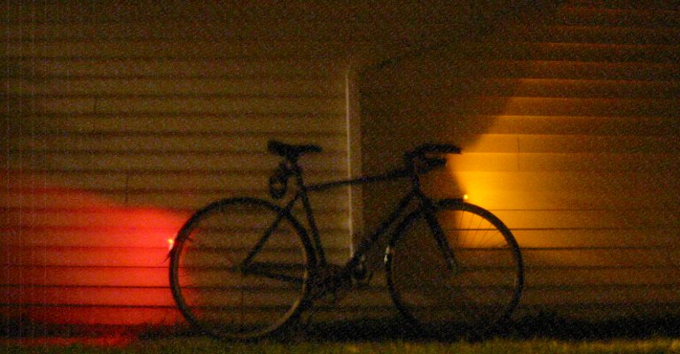
For those that can relate; this was taken at F2.8 and ASA 400. This shows a single flash. In terms of sending light in all possible directions we are doing quite good. Too good really, a lot of the light ends up either in space or on the ground. Better optics could help here but those optics would have to be larger than what I have now. Fortunately we have quite a lot of light available to waste.
Speaking of waste, you can adjust the brightness of the flashes by adjusting the charging resistors (R5, R7, R9, R10). Reducing them to 15 ohms would get you up to into 0.9A pulse range. I am fairly certain that the resulting system would be reliable. It would however drain the battery more than twice as fast. I don't think it would really get you any more attention (at least of the positive kind).
To speed up the flash rate you can reduce the value of R1. Halving the value of R1 would get you a pulse rate of 2 per second and a flash brightness of half at more or less the same battery consumption. The brightness could be restored by halving the value of the charging resistors (as mentioned in the previous paragraph) at the cost of twice the battery drain.
Speaking of batteries, this system would work well with a NiMH cell. In fact it would provide a more or less constant voltage/light output over the useful battery life. A NiMH cell has a high current capacity so a NiMH AA cell charged every week or so would likely be optimal.
I looked up the local laws with respect to bicycle lighting to try to determine if a front and back flasher system is legal. As far as I can determine it is not. I don't think anything someone might actually use for lighting in this century would be. It has been a long time since the laws were updated. I guess I'll just have to live with the uncertainty. Around here the only reason law enforcement does not spontaneously do something like hand out a safety award when a bicycle/rider combination is seen emitting light at night is because they are afraid they might be up to something.
The other research inspired by this project was night time bicycle safety in general. From my experience a bright flashing light on the front of the bike pretty much eliminates the common case of collisions caused by cars turning left across the path of the bike. The other common collision occurs when a car pulls out of a side street/driveway. I have often seen a driver glance in my direction between the flashes before deciding to go. This could be expected to reduce the problem to the fully stealthed bike/rider case. Unfortunately there is a complication. At some point during the manoeuvre the driver will see the next flash in their peripheral vision. Then their behaviour becomes impossible to predict. One of three things will happen:
- They will slam on the brakes.
- They will hit the accelerator.
- Those driving at the very edge of their ability will go into overload mode. This will produce a situation where there is a driverless car on the road for a time.
posted at: 14:57 | path: /ledlight | permanent link to this entry