Among other things, hacking is seeing the value in that which is considered worthless by less insightful people. This section is about making old TV antennas work in the exciting new world of digital television.
In most places in the world the same frequency allocations are used for digital TV as was used for analog TV. This makes sense as TV takes a lot of bandwidth. There isn't really any place to move it to. In North America some of the higher channels (part of the UHF band) have been reassigned to other purposes. Some of the lower channels (all of the VHF-low band) have been more or less deliberately abandoned by the broadcasters. That is because noise tends to be stronger at lower frequencies and there tends to be a lot of noise around these days. This means that in North America we are normally looking for antennas that work in the VHF-high and the lower portion of the UHF band.
You can often get an idea of the sort of raw material available by simply looking for abandoned antennas on roofs. Here is a common sight in the city of Winnipeg:
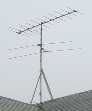
From having lived through the era I know that the top antenna with all the elements is likely optimized for receiving a faint signal on channel 12. That antenna was also expected to receive a strong signal on channel 7. Both of these are in the UHF-high band. I want to receive digital signals on channel 7 and 13 so the top antenna is of interest. The bottom antenna was used for receiving channels 6 and 3 in the VHF-low band. My local broadcasters have, as expected, abandoned this band so the lower antenna is of no interest to me.
In most cases you will not know the history of the old antennas you find scattered about the landscape. Then you need to do a bit more work.
TV antennas are made out of conductive rods called elements. The elements go perpendicular to the transmitter and are the active part of the antenna. Parts of the antenna that point directly towards the transmitter are inactive and are usually just there to support the elements. Often times the entire antenna is electrically connected. This doesn't make intuitive sense so it is important to realize that the centre of an element is normally electrically inactive.
One of the elements will be connected to the wire that goes to the TV. First measure the length of the connected element closest to the TV in metres. This element will normally be a half wavelength corresponding to one of the channels the antenna is designed to receive. Plug your measured length into this formula:
             150
Frequency = ------
            Length
The result is frequency in Megahertz(MHz). Consult with a table that
maps your local channels/bands to frequency and use it to find a
channel and band
(TV
channel frequencies). If your antenna has a bunch of elements that
are more or less the same size (like the ones in the preceding
picture) then you know the band and have a pretty good idea of what
channel the antenna is optimized for. If the antenna has a bunch of
different sized elements then you really only know one of the bands it
works at. Chances are it is supposed to work over that entire band. If
there are other elements connected to wires then you can measure them
and assume that the antenna works for the band(s) you come up with as
well. If the antenna has wires connected to all the elements
(log-periodic)
then you can try measuring the longest and shortest to get some idea
of the range of the antenna. If none of the elements are anywhere
close to the length required for any of your bands of interest then
you can reject that particular antenna without further thought. You
can try cheating by looking at pictures of antennas on a manufacturer
web site
(Winegard, Channel
Master, Antennas
Direct) relevant to your part of the world.
TV antenna elements are usually made from aluminium. As a result they will last pretty much forever in a non-corrosive outdoor environment. The best forgotten antennas are those that have never been outside at all. These can be found in the attics of houses with previous owners that were interested in not falling off the roof even once. Estate sales and older relatives are possible sources of these antennas.
In the case of an antenna that has spent a lot of time outside, pretty much everything other than the elements themselves and the support structure will be suspect. You will normally have to replace any nuts and bolts that are electrically important. Stainless steel hardware should be used if possible. Any connections will likely have to be redone. Any elements that are non-contiguous (these are sometimes arranged to fold) should be checked for continuity. Continuity between the elements and the support structure is normally unimportant.
I recently was made aware of an intriguing idea for antenna connections at a site I have also recently lost the reference to. The idea is to use stainless steel flat washers to prevent the wire and the aluminium element from coming into direct contact (causes corrosion). The only catch that I can see is that the flat washers would not be able to produce really high contact pressures by themselves. Thus the bolt would have to be made very tight. Here is how I managed that on one of my antennas:
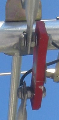
After splitting the plastic insulator due to excess pressure I ended up having to use a nut for tightening and a nut to hold the end of the element in place. That allowed me to tighten the connection to the point where the copper wire just started to deform. Starting from the left end of one of the terminals shown in the picture you are seeing; screw head, flat washer, wire, flat washer, element, self locking nut, insulator, self locking nut. All the hardware shown is of course stainless steel.
Fiddling with connections ends up being the primary maintenance task for an outside TV antenna. Thus it is well worth the time to explore ideas that could potentially increase the number of years between trips to the roof.
Most digital tuners/TVs will show you some sort of signal strength indicator for the currently tuned channel. If you can run a cable to a relatively open area you can get some sort of idea of the performance of your antenna by swinging it around. If the signal is significantly higher when you point the antenna at the transmitter then that is good. If the antenna works pretty much just as well pointed straight up (for instance) then that is bad.
Edit: proceeding -> preceding
Edit: will -> well
posted at: 10:13 | path: /tv | permanent link to this entry