The Call of the Open Sidewalk
From a place slightly to the side of the more popular path
[
Home
|
About
|
RSS
|
ATOM
|
Archives: 2013
2012
2011
2010]
Sat, 18 May 2013
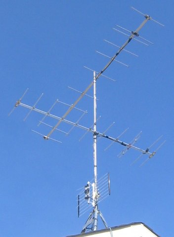
A friend and myself built more or less the same antenna as described previously:
In this case the antennas were all new. The interesting thing here is
that the cost of the three simple antennas was actually somewhat
competitive with the cost of a single complex antenna
($20+$20+$13=$53CAN). There is something to be said for creating a
complex antenna out of simple parts particularly in the case of a
difficult RF environment.
Here are the results:
| Channel |
Strength |
Quality |
| 7 |
90% |
90% |
| 13 |
78% |
98% |
| 27 |
100% |
100% |
| 35 |
75% |
86%-100% |
| 40 |
100% |
82%-96% |
| 51 |
100% |
100% |
The results for the two VHF-high band channels (7,13) are a bit worse
than those described for the first antenna. That's probably because
the new project used 5 element antennas. The original one used
recovered 11 element antennas. Since we were paying for the antennas
we settled for good enough.
These results were measured after a 4 way splitter as was the case
with the first antenna. The new antenna site was 1 km west of the old
one.
posted at: 15:06 |
path: /tv |
permanent link to this entry
Wed, 14 Dec 2011
Here are the other articles in this series:
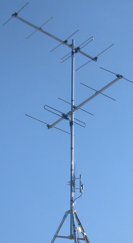
Here is what the antenna looks like:
Doesn't that look great? Pure function...
The support structure is a 10 foot chain link fence top rail bought at
the local home improvement store. It is attached to the roof with a
tripod sold as an antenna support. The top antenna points at channel
13. The middle antenna points at channel 7. The bottom antenna (low
gain UHF band) receives channels 27, 35, 40 and 51 and points between
the transmitters. The cables are held to the mast with multiple wraps
of black vinyl electrical tape, which seems to be the local custom.
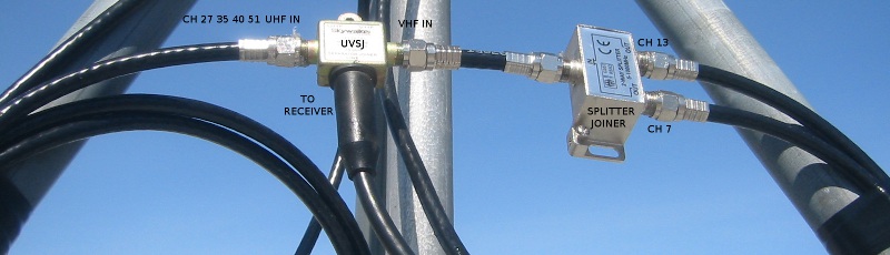
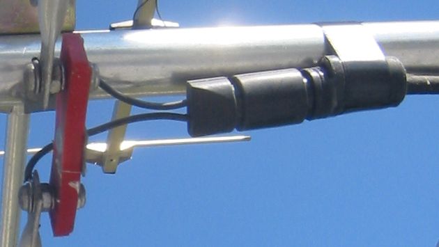
Here is the place where the signals are combined:
Here is the place where I ground the antenna:
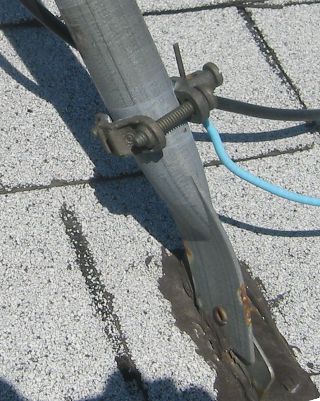
The requirements for grounding things like TV antennas are different
from place to place. If you can't manage to ground it exactly as
required, don't just give up. Ground it as best you can. You should
ground the outside conductor of the cable where it comes into the
building as well. You can buy a thing called a grounding block to make
this convenient.
As the digital TV conversion is finally complete in my area I can
provide results:
| Channel |
Strength |
Quality |
| 7 |
90% |
100% |
| 13 |
87% |
100% |
| 27 |
86% |
100% |
| 35 |
80% |
94% |
| 40 |
94% |
80%-100% |
| 51 |
63% |
75% |
Strength is proportional to the level of the signal. Quality is a
measure of how certain the demodulator can be that a particular bit is
a 0 or a 1 (higher is better). Channels 7 and 13, each with a
dedicated high gain antenna, are as would be expected quite good. The
rest of the channels are fairly good with the exception of channel
51. I have no real explanation for this. The transmitter is less than
3 km away. The quality of channel 40 is fluctuating. That is probably
due to either noise or a reflection that is changing faster than the
receiver can compensate.
posted at: 17:18 |
path: /tv |
permanent link to this entry
Wed, 07 Dec 2011
Creating a usable over the air (OTA) TV antenna system is one of those
things that usually involves a significant amount of experimentation
... but you have to start somewhere.
A good place to start is with the worst signal you want to
receive. Here is the important bit from
my TV Fool report (as discussed in
a previous
post):
The farthest transmitter in our list of desired channels (7 13 27 35
40 51) is channel 13 at 41km (25.2 miles). Applying a realism filter
to the claims of the people that make TV antennas, we come up with a
requirement for some sort of medium gain antenna. How about we specify
an antenna that does both our bands of interest and just point it at
the channel 13 transmitter? This, by the way, is all we have to do in
most situations. Deal with the worst and hope for the rest.
We would then have the close 27 40 and 51 directly behind the
transmitter. Good. Most antennas work reasonably well to the rear. We
unfortunately have 7 and 35 that are not so close and they are pretty
much at right angles to the antenna. Most antennas are quite good at
rejecting signals to the side. The solution here is to rotate the
antenna so it points between 13 and 7/35. Lower gain antennas are
better at receiving stations over a wider angle so we might be better
off downgrading to a low gain antenna ... an unhappy but common
compromise.
If I was in a more rural environment I might be done. I am instead in
what might be termed a high density suburban area. My neighbours all
have cable and do not have to bother with interference caused by their
electronics. I am not blameless with respect to interference
either. Low gain antennas are also good at receiving noise over a
wider angle. I used to use a single low gain antenna in the analog
days and had to live with all the received noise.
We go on ...
Before we unleash the dogs of complexity we might want to think about
our available assets. I just happen to have a couple of high
gain recovered
antennas that are optimized for channel 12 and were expected to
work reasonably well on channel 7.
Channel 7 is on our list. So that just works. Channel 13 is only a few
percent different from channel 12 in terms of radio frequency. It
would have a lot of gain when used on channel 13. Unfortunately the 13
and 7 transmitters are are at right angles so a single high gain
antenna is the last thing we want here.
We have two antennas available. I didn't pay anything for the
antennas. Why not point each antenna directly at a transmitter?
In the analog days the answer to the proceeding questions would of
been; ghosts otherwise
known as reflections. The antenna pointing in the wrong direction for
the desired channel would receive reflections quite well. Special
filters were required to eliminate these reflections. Digital TV is
very good at cancelling out these reflections
(relevant
post). As a result, multiple antennas can work quite well here in
the 21st century.
You can combine the signals with
a splitter/joiner:
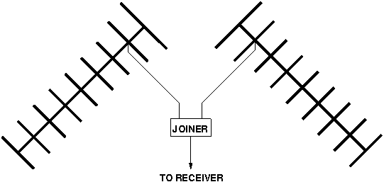
If your antennas are pointing in more or less the same or opposite
directions you should make the cables between the antennas and the
joiner the same length. That is in the hope that the two signals will
add together rather than cancel. In our right angle case it doesn't
really matter. If you have matching transformers on one of both of the
antennas you should reverse the antenna connections on one of them to
see if things get better.
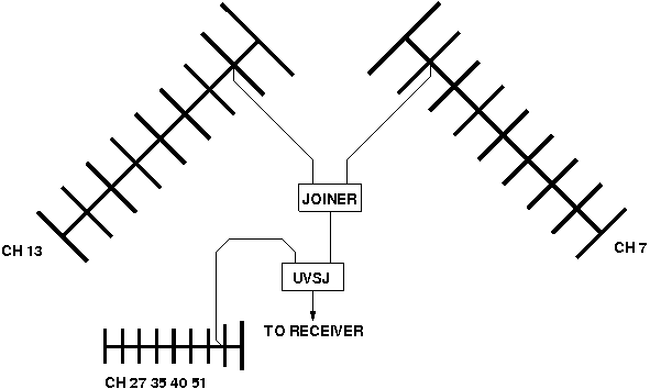
That takes care of channels 7 and 13 leaving 27, 35, 40, and 51. Here
we finally get lucky. With 7 and 13 being in the VHF-hi band and 27-51
being in the UHF band we can use
a band
separator/joiner. In this case we want a UVSJ (UHF, VHF). The band
separator/joiner will completely isolate the 7 and 13 antennas which
allows us to consider the problem of receiving 27-51 with no
consideration of what we have done so far. Channel 35 is the only
remaining transmitter that is not right next door so we just use a low
gain UHF band antenna with the hope that we can find a magic angle
that will work for all 4 channels. This might work because the UHF
band is at a higher frequency where there is less woman made noise.
We end up with this:
This was a very specific example. The point here is that this can be a
reductionist process. That can make this a lot of fun for those that
are into that type of thinking.
We now have a configuration we can build and try out...
posted at: 15:04 |
path: /tv |
permanent link to this entry
Thu, 18 Aug 2011
OK, what do we need to know to design our over the air (OTA) TV antenna system?
What channels do we wish to receive?
There will likely be
compromises. It is a good idea to spend some time thinking about what
sort of compromises you would be willing to make. If you are doing
this entirely for the technical challenge, then the answer to the
question might be "All the channels that are humanly possible to
receive from my location." If you are all or partially doing this for
the TV then you will likely end up with three lists; Mission Critical
(I need these to consider doing the project), Optional, and Don't care.
Where are the transmitters for these channels?
This is
normally a matter of public record. The appropriate government agency
web site will likely have the coordinates of the local TV transmitters
that you can plot on a map. You want to have some idea of where you
have to aim the antenna.
How strong are the signals from these transmitters?
The
signal gets stronger when; the transmitter is closer, the transmitting
antenna is higher, the transmitted power (measured as ERP in Watts)
is greater. Signal strength is hard to predict so this is going to be
a guess even with the best available information. If you have any TV
antenna using neighbours you can ask them what channels they
see. Online OTA enthusiast forums can be sources of reception reports
for your area. In general you need larger antennas placed higher above
the ground to receive weaker signals.
In places with enlightened government agencies that provide TV
transmitter data in a usable form people will create web sites that
display this data in a way most useful to those messing around with TV
antennas. As an example, my favourite site of this kind
is TV Fool. After giving the site
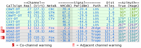
my location it gave me this:
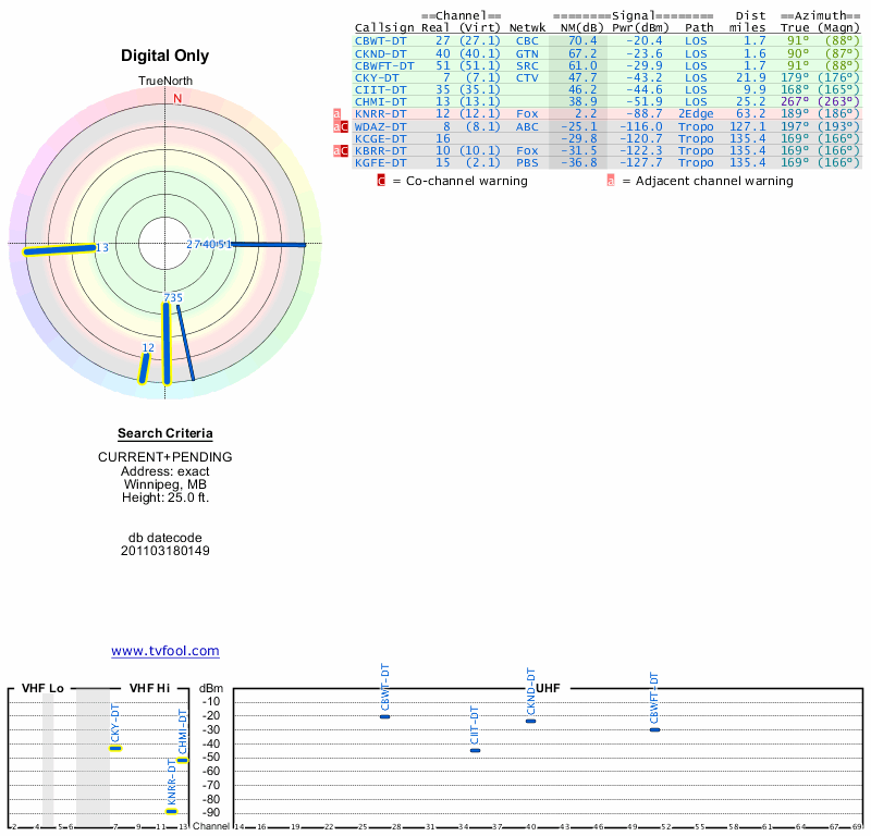
This site does some sort of modelling and comes up with a signal
strength as well as a direction and distance. This signal strength
information can be quite handy even if it is not entirely accurate but
for the purposes of this example I will ignore it.
What channels can we expect to receive? The people who make TV
antennas often claim that their very best efforts can receive signals
from as far away as 100km. This is under conditions few will ever see but
it makes a nice extreme limit. The distances given on the site are in
the delightfully quaint units of "miles" so I will translate into
something a little more mainstream as I go along. There are 6
transmitters within 100 km on channels 7, 13, 27, 35, 40,
51. Annoyingly, KNRR on channel 12 is more or less exactly at the 100
km distance (63.2 mi). I happen to know from the reports of others and
personal experience that this is a very difficult signal to receive at
my location ... so we will drop it. Receiving such a marginal signal
is well beyond the level of this discussion anyway. We will place all
6 channels on the Mission Critical list to keep things challenging.
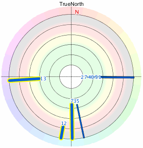
There is a tendency to locate TV transmitters that serve a particular
area in more or less the same place. That makes it possible for
everyone in that area to point a single antenna to receive
everything. Let's see how they did in my area...
So ... not so great. There are transmitters directly to the east,
transmitters directly to the south, and channel 13 by itself directly
to the west. This is starting to look bad. But let us now group the
transmitters in terms of band to get an idea of what sort of antennas
we might need. We only have two bands in use. VHF-hi (channels 7 and
13) and UHF (channels 27, 35, 40, 51). That's good. Let us now
consider each band separately. On VHF-hi we have channel 13 directly
west and channel 7 directly south. In other words, at right
angles. That's bad. On UHF we have channel 35 pretty much at right
angles to all the other channels. This is also bad but I note that the
UHF transmitters other than channel 35 are only about 3km (1.7 mi)
away. At that distance it is unlikely that we could do anything to
prevent the reception of those channels.
We now understand the problem. We must have enough information...
Edit: channel 13 -> channel 35
Edit: removed extra period
posted at: 22:48 |
path: /tv |
permanent link to this entry
Wed, 17 Aug 2011
Here I will do a show and tell with the important components used for
over the air (OTA) television ... but first let's talk about the past...
OTA television was the first kind of television. A kind of
transmission line
called twin lead
was used to get the signal from the antenna to the TV. Twin lead is
poorly shielded so the cable TV people used a kind of transmission
line known
as coaxial
cable to keep their private radio from interacting with the public
radio in the open atmosphere. This coaxial cable (AKA coax) eventually
became popular for OTA antenna work and the use of twin lead is
minimal these days.
This situation would seem to imply that there should be components
intended for use with with coaxial cable in cable applications that
could be used for OTA applications. This is mostly true.
This is what the coaxial cable might look like:
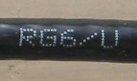
This type of cable is known as RG-6 or RG-6U. There are other types of
cable that will work but the discussion is a waste of time for pretty
much everyone. Just use RG-6.
You can buy your RG-6 from the local home improvement store without
too much fear of poor quality. Just ensure that the cable you get is
mechanically reasonable and has a black plastic covering (UV
resistance). The outer conductor should entirely cover the inner
conductor. This is often done with an extra layer of aluminium foil. Do
not kink or sharply bend your cable as this can damage it. If the
person at the store seems confused just tell them that you are
installing a satellite dish and you will likely be given RG-6.
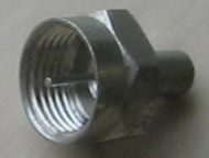
Front and rear views of a RG-6 compatible connector:
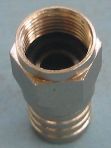
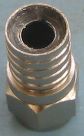
This is known as an
"F"
connector. The connector does not supply a centre conductor, instead
the bare copper conductor of the cable is used directly. This makes
the connector very quick to attach to the the cable. It also makes the
F connector very susceptible to corrosion. That means you you need to
find F connectors that are specifically designed to exclude water and
corrosive atmospheres. The connector pictured achieves this with
silicone grease in the slot where the cable is crimped and a rubber O
ring on the face of the connector. This is the crimping tool used with
this sort of F connector:
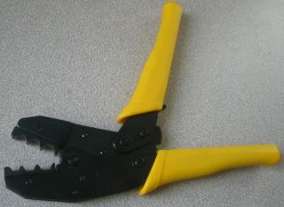
Note that the die on the crimping tool is as wide as the crimpable
part of the connector. This tool is relatively expensive so there is
always a temptation to use some other sort of tool to do the
crimping. Don't. The tool is pretty much impossible to damage or wear
out so it is a good candidate for some sort of shared cost
arrangement. Go to your favourite video sharing web site and watch
other people attach F connectors, then do a few practise attachments.
The F connector is threaded and will accept a wrench for
tightening. It is very easy to cause damage by overtightening this type
of connector. If you are not sure of yourself it is OK to just finger
tighten an F connector. Poor quality F connectors will often be hard
to thread on and/or will cause the cable to twist during the
tightening phase. This will not make any difference to the electrical
performance of the connector but it can be annoying.
There is another popular type of F connector called a compression type
available in a weatherproof version. These are reputed to work well
and should be investigated for new installations. They use their own
unique crimping tool.
So ... you want to ask the person in the store for F connectors
intended for outdoor applications that are compatible with RG-6 cable.
Here is a somewhat obscure part:
This is a dead end F connector with a resistor in it. It is called a
"terminator" as its primary purpose is to prevent electrical
reflections caused by the discontinuity at the end of an unconnected
transmission line. It also keeps the weather out of the connector and
the thing the connector is attached to. When you are done with your
antenna installation just screw one of these onto any open connectors.
Here's a "balun":
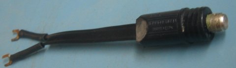
These are also known as matching transformers. The one shown is the
type intended for outdoor applications. A balun bridges the world of
classic twin lead transmission line and the more commonly used coaxial
cable. Many antennas are still designed for the use of twin lead. If
your antenna has screw terminals instead of of an F connector then you
need to add a balun like this:
The F connector on the balun is covered by a rubber boot intended to protect it from the elements.
This type of weatherproof balun is only used for OTA antenna
systems. This means that the manufacturer is expected to produce
something with adequate performance for the application. Unfortunately,
poorly performing baluns are still fairly common.
This might be a part you will want to buy online. Online retailers
that specialize in OTA parts will sometimes provide performance
claims (the lower the loss the better). Baluns branded by makers of TV
antennas are usually intended to make the primary product sold work
well. As a result "antenna brand" baluns can be expected to be not all
that terrible. Online OTA enthusiast forums can be a source of tests
of popular brands.
Here are some splitters:
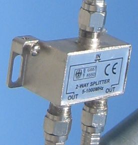
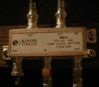
The thing that is "split" here is the signal. These are normally used
to distribute a signal from an OTA antenna to several TVs and/or
tuners. Those of us hung up on the first law of thermodynamics will
have to acknowledge that this process has to cause a loss of signal on
each leg of the splitter. This sort of thought produces the result
that a 2-way splitter has a minimum loss of 3 dB (half power) and a
4-way splitter has a minimum loss of 6 dB (quarter power). A good
quality splitter should not be responsible for more than a few extra
dB on top of the theoretical best performance. A good 2-way splitter
could have a a loss of 3.5 dB (67% of the signal remains) and a good
4-way splitter could have a loss of 7 dB (45% of the signal remains).
There is normally little uncertainty about the performance of
splitters found at random local stores. In most places splitters are
mostly used to split cable TV which involves very high signal
levels. If the resultant splitter lets any small fraction of the
signal through the customer will be happy. It is not like the buyer is
going to have the equipment to check. As a result these things are
sold with performance that ranges from the terrible to the hilarious.
My comments about having to order your baluns online thus apply to
splitters as well. Sometimes an electronic retailer will have two
levels of splitter with one of them having a price that is two to
three times the other for no apparent reason. The expensive one is
possibly intended for OTA use. The splitters that are rated to work up
to a frequency of 2000 MHz are intended for satellite TV use. They
will work but are normally a waste of money. Sometimes you might be
forced to buy the satellite TV version if it is the only one available
with a good claimed signal loss specification.
A band separator/joiner:
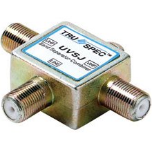
This is actually a sort of analog signal processor. When a signal is
fed into the common input (separator) the device will produce two new
signals with the channels from the wrong band filtered out on each
side. It causes very little signal loss while doing so. For example, a
UHF/VHF separator/joiner will produce two outputs; one with all the
UHF channels, and one with all the VHF channels. This was very useful
in the days when TVs had separate UHF and VHF inputs as it allowed the
use of a single cable to carry signals from both bands from the roof.
These days they are more often used in the other direction for their
joiner function. For example, a UHF/VHF separator/joiner makes it
possible to combine the channels received by a UHF antenna with the
channels received by a VHF antenna with virtually no loss. Extraneous
signals from the band that each respective antenna is not designed to
receive would be filtered out.
Here is some silicone grease:
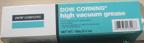
This is more of a consumable than a part. The cool kids like to smear
this stuff on and in any connectors/connections in an attempt to delay
corrosion. The grease shown is actually intended to seal laboratory
glassware. It was expensive but some random internet commenter claims
that this stuff is the best ever for antenna work. That's good enough
for me.
I will say one thing for the "DOW CORNING(R) high vacuum grease". It
is impossible to entirely remove remove it from anything. That
included me. You pretty much have to wait until the thin film on
yourself and your surroundings gets spread out enough so it is no
longer perceptible. I guess that means it is actually good or
something.
Another consumable:
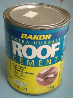
If you are planning to make holes in a roof as part of your schemes it
is a good idea to have a small supply of a patching material
appropriate to the type of roof. Eventually you will do something less
than optimal and things will suddenly turn into a basic shelter
issue. This is boring and can detract from your enjoyment of the
primary activity. This is particularly true if there are other people
living in the house that do not share your enthusiasm for this
activity.
Edit: silicon -> silicone
posted at: 15:40 |
path: /tv |
permanent link to this entry
Powered by PyBlosxom