Here I will do a show and tell with the important components used for over the air (OTA) television ... but first let's talk about the past...
OTA television was the first kind of television. A kind of transmission line called twin lead was used to get the signal from the antenna to the TV. Twin lead is poorly shielded so the cable TV people used a kind of transmission line known as coaxial cable to keep their private radio from interacting with the public radio in the open atmosphere. This coaxial cable (AKA coax) eventually became popular for OTA antenna work and the use of twin lead is minimal these days.
This situation would seem to imply that there should be components intended for use with with coaxial cable in cable applications that could be used for OTA applications. This is mostly true.
This is what the coaxial cable might look like:
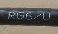
This type of cable is known as RG-6 or RG-6U. There are other types of cable that will work but the discussion is a waste of time for pretty much everyone. Just use RG-6.
You can buy your RG-6 from the local home improvement store without too much fear of poor quality. Just ensure that the cable you get is mechanically reasonable and has a black plastic covering (UV resistance). The outer conductor should entirely cover the inner conductor. This is often done with an extra layer of aluminium foil. Do not kink or sharply bend your cable as this can damage it. If the person at the store seems confused just tell them that you are installing a satellite dish and you will likely be given RG-6.
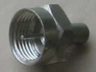
Front and rear views of a RG-6 compatible connector:
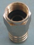
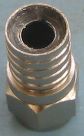
This is known as an "F" connector. The connector does not supply a centre conductor, instead the bare copper conductor of the cable is used directly. This makes the connector very quick to attach to the the cable. It also makes the F connector very susceptible to corrosion. That means you you need to find F connectors that are specifically designed to exclude water and corrosive atmospheres. The connector pictured achieves this with silicone grease in the slot where the cable is crimped and a rubber O ring on the face of the connector. This is the crimping tool used with this sort of F connector:
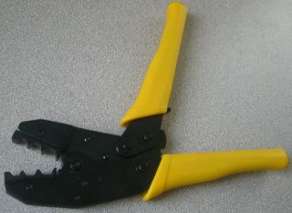
Note that the die on the crimping tool is as wide as the crimpable part of the connector. This tool is relatively expensive so there is always a temptation to use some other sort of tool to do the crimping. Don't. The tool is pretty much impossible to damage or wear out so it is a good candidate for some sort of shared cost arrangement. Go to your favourite video sharing web site and watch other people attach F connectors, then do a few practise attachments.
The F connector is threaded and will accept a wrench for tightening. It is very easy to cause damage by overtightening this type of connector. If you are not sure of yourself it is OK to just finger tighten an F connector. Poor quality F connectors will often be hard to thread on and/or will cause the cable to twist during the tightening phase. This will not make any difference to the electrical performance of the connector but it can be annoying.
There is another popular type of F connector called a compression type available in a weatherproof version. These are reputed to work well and should be investigated for new installations. They use their own unique crimping tool.
So ... you want to ask the person in the store for F connectors intended for outdoor applications that are compatible with RG-6 cable.
Here is a somewhat obscure part:
This is a dead end F connector with a resistor in it. It is called a "terminator" as its primary purpose is to prevent electrical reflections caused by the discontinuity at the end of an unconnected transmission line. It also keeps the weather out of the connector and the thing the connector is attached to. When you are done with your antenna installation just screw one of these onto any open connectors.
Here's a "balun":
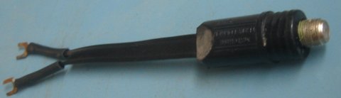
These are also known as matching transformers. The one shown is the type intended for outdoor applications. A balun bridges the world of classic twin lead transmission line and the more commonly used coaxial cable. Many antennas are still designed for the use of twin lead. If your antenna has screw terminals instead of of an F connector then you need to add a balun like this:
The F connector on the balun is covered by a rubber boot intended to protect it from the elements.
This type of weatherproof balun is only used for OTA antenna systems. This means that the manufacturer is expected to produce something with adequate performance for the application. Unfortunately, poorly performing baluns are still fairly common.
This might be a part you will want to buy online. Online retailers that specialize in OTA parts will sometimes provide performance claims (the lower the loss the better). Baluns branded by makers of TV antennas are usually intended to make the primary product sold work well. As a result "antenna brand" baluns can be expected to be not all that terrible. Online OTA enthusiast forums can be a source of tests of popular brands.
Here are some splitters:
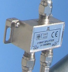
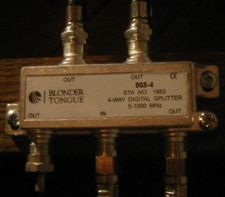
The thing that is "split" here is the signal. These are normally used to distribute a signal from an OTA antenna to several TVs and/or tuners. Those of us hung up on the first law of thermodynamics will have to acknowledge that this process has to cause a loss of signal on each leg of the splitter. This sort of thought produces the result that a 2-way splitter has a minimum loss of 3 dB (half power) and a 4-way splitter has a minimum loss of 6 dB (quarter power). A good quality splitter should not be responsible for more than a few extra dB on top of the theoretical best performance. A good 2-way splitter could have a a loss of 3.5 dB (67% of the signal remains) and a good 4-way splitter could have a loss of 7 dB (45% of the signal remains).
There is normally little uncertainty about the performance of splitters found at random local stores. In most places splitters are mostly used to split cable TV which involves very high signal levels. If the resultant splitter lets any small fraction of the signal through the customer will be happy. It is not like the buyer is going to have the equipment to check. As a result these things are sold with performance that ranges from the terrible to the hilarious.
My comments about having to order your baluns online thus apply to splitters as well. Sometimes an electronic retailer will have two levels of splitter with one of them having a price that is two to three times the other for no apparent reason. The expensive one is possibly intended for OTA use. The splitters that are rated to work up to a frequency of 2000 MHz are intended for satellite TV use. They will work but are normally a waste of money. Sometimes you might be forced to buy the satellite TV version if it is the only one available with a good claimed signal loss specification.
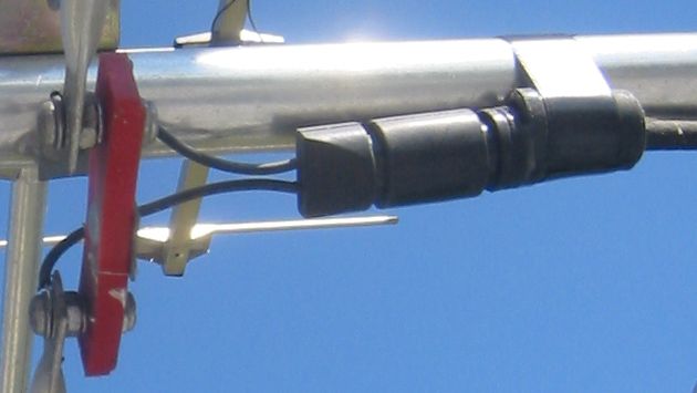
A band separator/joiner:
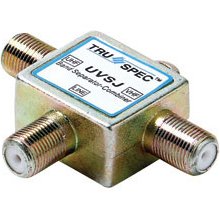
This is actually a sort of analog signal processor. When a signal is fed into the common input (separator) the device will produce two new signals with the channels from the wrong band filtered out on each side. It causes very little signal loss while doing so. For example, a UHF/VHF separator/joiner will produce two outputs; one with all the UHF channels, and one with all the VHF channels. This was very useful in the days when TVs had separate UHF and VHF inputs as it allowed the use of a single cable to carry signals from both bands from the roof.
These days they are more often used in the other direction for their joiner function. For example, a UHF/VHF separator/joiner makes it possible to combine the channels received by a UHF antenna with the channels received by a VHF antenna with virtually no loss. Extraneous signals from the band that each respective antenna is not designed to receive would be filtered out.
Here is some silicone grease:
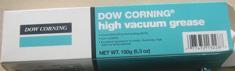
This is more of a consumable than a part. The cool kids like to smear this stuff on and in any connectors/connections in an attempt to delay corrosion. The grease shown is actually intended to seal laboratory glassware. It was expensive but some random internet commenter claims that this stuff is the best ever for antenna work. That's good enough for me.
I will say one thing for the "DOW CORNING(R) high vacuum grease". It is impossible to entirely remove remove it from anything. That included me. You pretty much have to wait until the thin film on yourself and your surroundings gets spread out enough so it is no longer perceptible. I guess that means it is actually good or something.
Another consumable:
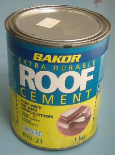
If you are planning to make holes in a roof as part of your schemes it is a good idea to have a small supply of a patching material appropriate to the type of roof. Eventually you will do something less than optimal and things will suddenly turn into a basic shelter issue. This is boring and can detract from your enjoyment of the primary activity. This is particularly true if there are other people living in the house that do not share your enthusiasm for this activity.
Edit: silicon -> silicone
posted at: 15:40 | path: /tv | permanent link to this entry